Back And Forth Motion System
Categories: Mechanical Lab Equipment ManufacturerBack And Forth Motion System Functioning principle Back And Forth Motion System use a back and forth motion case UHING, mechanism which transforms the continuous rotation motion of a smooth shaft in a...


Product
Description
Back And Forth Motion System
Functioning principle
Back And Forth Motion System use a back and forth motion case UHING, mechanism which transforms the continuous rotation motion of a smooth shaft in a linear back and forth motion. Cinematically, it is like a screw-nut system. However two supplementary functionalities can be achieved : the setting of the thread of the screw-nut system and the change of the thread direction (helix on the left or on the right). This last functionality allows to change the displacement direction of the case. Otherwise, thanks to a special feature, the inversion of the translation direction of the case is almost instantaneous.
These mechanisms are used a lot in the winding techniques. They are used to distribute correctly the wires or the cables on a bobbin. Technically, for this operation, it is important to check:
-
The reversing speed which conditions the quality of the winding .
-
The non sliding between the interior rings of the bearings considering as the nut and the shaft whatever is the acceleration of the case.
-
The non sliding during the loading of the case
Teaching Objectives of Back And Forth Motion System
This system allows to make practical works in the fields of the Mechanical engineering and electrical engineering:
This system has a high-level mechanical aspect because of the complexity of the reversing and setting thread motion transformation case. It allows to study the functional analysis of the different functions:
-
To measure the performances of the system (thread setting, transmissible effort before sliding.
-
To cinematically model the UHING system (contact shaft – bearing ring, thread setting system.
-
To make a computer simulation (SolidWorks) in relation to the thread setting and direction change subsystems.
-
The electrical and control aspects are also very important with the Direct Current motor and its 4 quadrants speed driver, the instrumentation (speed, position and force sensors).
Practical works list:
- Discovery of the system and internal functional analysis.
- Experimental verification of the performances.
- Kinematics’ computer simulation
- Computer simulation of the thread setting
- Computer simulation of the direction change
- Measurement of the performances. Reversing time and thread
- Study and measurement of the sliding.
- Implementation of a winding operation. Associated setting
- Closed loop control. Identification of the system
- Quadrants functioning of the speed driver
Technical Specifications of Back And Forth Motion System
A testing bench including
- A USING case mounted on support with device to implement a winding operation. Two bobbins allow to adjust the device and to achieve this operation with wires of different diameters
- A direct current motor
- Some sensors allow to measure in real time:
-
The rotational speed of the motor by a tachometer
-
The speed of transfer of the case by a tachogenerator
-
The motor current, picture of the torque
-
The angular position of the bearing axis similar to a nut according to the time during the reversing time by a potentiometer sensor.
-
A force sensor allowing to test limits sliding force.
A control cabinet including:
- A 4 quadrants electronic speed driver. The input set points imposed to the motor by the speed driver are of the type :step, ramp and sinusoid speed.
- A data acquisition card National Instruments allow to reach a frequency of 10 000 Hz.
- This level of measurement allows to study the reversing phase which last about 0,1 second.
- A digital transmitter for the rotational speed of the motor.
- A switch for working in manual or software mode.
- A control and data acquisition software
- Using case for manipulation.
- Case with cover made of Plexiglas® allowing the visualization of the mechanical functioning of the system (setting of the thread and change of direction)
Essential requirements
- A PC computer with Windows® XP OS.
- SolidWorks® and MECA 3D® software.
- Power supply : 220V - 50 Hz.
Dimensions and weight
- Testing bench : 820 x 500 x320 mm - 20 kg
- Control cabinet : 420 x 410 x 700 mm - 10 kg
quick overview :
Back And Forth Motion System
Functioning principle
Back And Forth Motion System use a back and forth motion case UHING, mechanism which transforms the continuous rotation motion of a smooth shaft in a linear back and forth motion. Cinematically, it is like a screw-nut system. However two supplementary functionalities can be achieved : the setting of the thread of the screw-nut system and the change of the thread direction (helix on the left or on the right). This last functionality allows to change the displacement direction of the case. Otherwise, thanks to a special feature, the inversion of the translation direction of the case is almost instantaneous.
These mechanisms are used a lot in the winding techniques. They are used to distribute correctly the wires or the cables on a bobbin. Technically, for this operation, it is important to check:
-
The reversing speed which conditions the quality of the winding .
-
The non sliding between the interior rings of the bearings considering as the nut and the shaft whatever is the acceleration of the case.
-
The non sliding during the loading of the case
Teaching Objectives of Back And Forth Motion System
This system allows to make practical works in the fields of the Mechanical engineering and electrical engineering:
This system has a high-level mechanical aspect because of the complexity of the reversing and setting thread motion transformation case. It allows to study the functional analysis of the different functions:
-
To measure the performances of the system (thread setting, transmissible effort before sliding.
-
To cinematically model the UHING system (contact shaft – bearing ring, thread setting system.
-
To make a computer simulation (SolidWorks) in relation to the thread setting and direction change subsystems.
-
The electrical and control aspects are also very important with the Direct Current motor and its 4 quadrants speed driver, the instrumentation (speed, position and force sensors).
Practical works list:
- Discovery of the system and internal functional analysis.
- Experimental verification of the performances.
- Kinematics’ computer simulation
- Computer simulation of the thread setting
- Computer simulation of the direction change
- Measurement of the performances. Reversing time and thread
- Study and measurement of the sliding.
- Implementation of a winding operation. Associated setting
- Closed loop control. Identification of the system
- Quadrants functioning of the speed driver
Technical Specifications of Back And Forth Motion System
A testing bench including
- A USING case mounted on support with device to implement a winding operation. Two bobbins allow to adjust the device and to achieve this operation with wires of different diameters
- A direct current motor
- Some sensors allow to measure in real time:
-
The rotational speed of the motor by a tachometer
-
The speed of transfer of the case by a tachogenerator
-
The motor current, picture of the torque
-
The angular position of the bearing axis similar to a nut according to the time during the reversing time by a potentiometer sensor.
-
A force sensor allowing to test limits sliding force.
A control cabinet including:
- A 4 quadrants electronic speed driver. The input set points imposed to the motor by the speed driver are of the type :step, ramp and sinusoid speed.
- A data acquisition card National Instruments allow to reach a frequency of 10 000 Hz.
- This level of measurement allows to study the reversing phase which last about 0,1 second.
- A digital transmitter for the rotational speed of the motor.
- A switch for working in manual or software mode.
- A control and data acquisition software
- Using case for manipulation.
- Case with cover made of Plexiglas® allowing the visualization of the mechanical functioning of the system (setting of the thread and change of direction)
Essential requirements
- A PC computer with Windows® XP OS.
- SolidWorks® and MECA 3D® software.
- Power supply : 220V - 50 Hz.
Dimensions and weight
- Testing bench : 820 x 500 x320 mm - 20 kg
- Control cabinet : 420 x 410 x 700 mm - 10 kg
Product
Reviews
add Review
reviews
No Review Yet.
Related
Products
The apparatus consists of converging diverging circular tes...
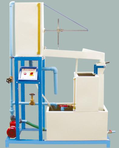
Impact Of Jet Apparatus It can measure the force generated b...
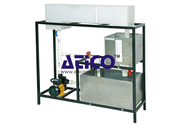
Losses In Pipe To determine minor flow losses(Fittings) in...
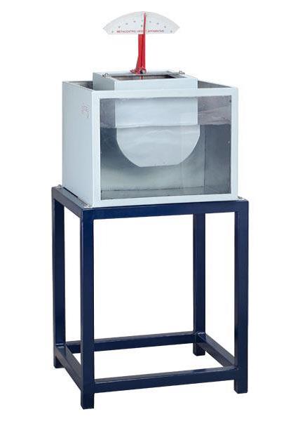
Metacentric Top Equipment Fundamentals of Buoyancy, Metacent...
Notch and Weir Apparatus Notches or Weirs are kept in the p...
Orifice and Mouthpiece Apparatus
Orifice and Mouthpiece Apparatus Both orifices and mouthpiec...
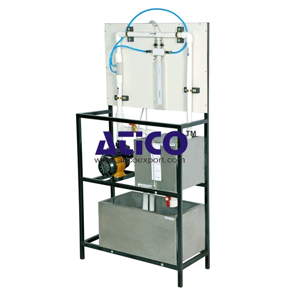
Orifice Meter This equipment is designed to introduce colle...
Pipe Friction Equipment Main Losses In Pipe (Losses Due To...
Product
Reviews
add Review
reviews
No Review Yet.