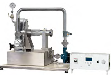
Computerized Pelton Turbine Bench
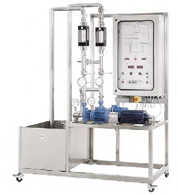
Categories: Fluid MechanicsThe bench is a computerized table-top unit for the study of the technical characteristics of the Pelton hydraulic turbine. The unit is real and totally operational: in fact, it allows to modify the op...


Product
Description
quick overview :
Product
Reviews
add Review
reviews
No Review Yet.
Related
Products
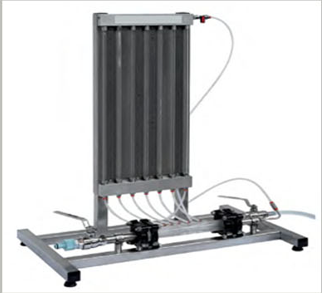
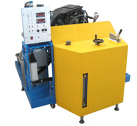
Equipment For Air Flow Studies
Description The equipment comprises a long smooth walled...
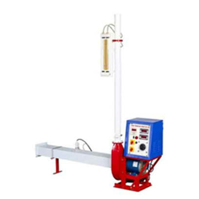
Bernoulli's Theorem Demonstration
Bernoulli's Theorem Demonstration Manufacturer and SupplierT...
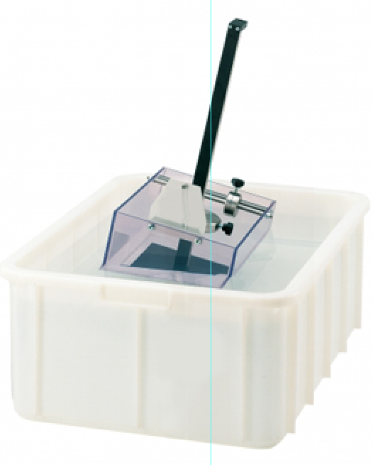
Stability of Floating BodiesIn hydrostatics, the metacentre...
The unit allows to carry out a vast selection of tests on au...
This unit has been designed to study the main equations corr...
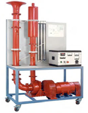
Centrifugal Air Compressor Study Unit
The study unit allows to study the main characteristics of a...
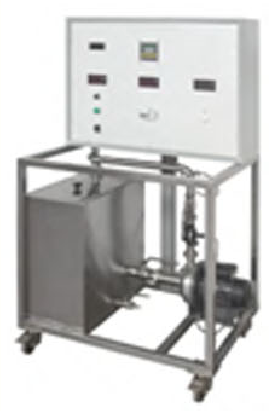
Centrifugal Multi-Pump Test Bench
The teaching unit is a modular group designed to perform com...
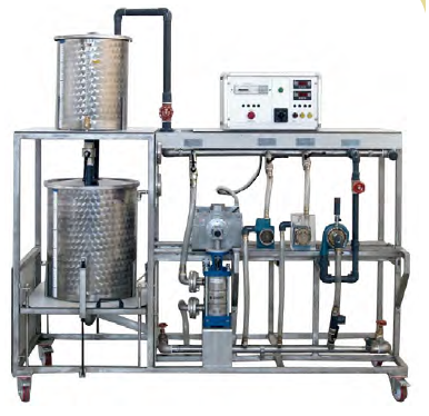
Centrifugal Pump in Series and Parallel...
Transfer and circulation of liquids in networks and pipes is...
Copyrights © 2025 All Rights Reserved by Atico
Product
Reviews
add Review
reviews
No Review Yet.