Determining Gauge Factor of Strain Gauges
Categories:Determining Gauge Factor of Strain Gauges Technical Description: As universal aids to experimental stress and strain analysis, strain gauges enable mechanical strain to be converted into electrical s...
Product
Description
Determining Gauge Factor of Strain Gauges
Technical Description:
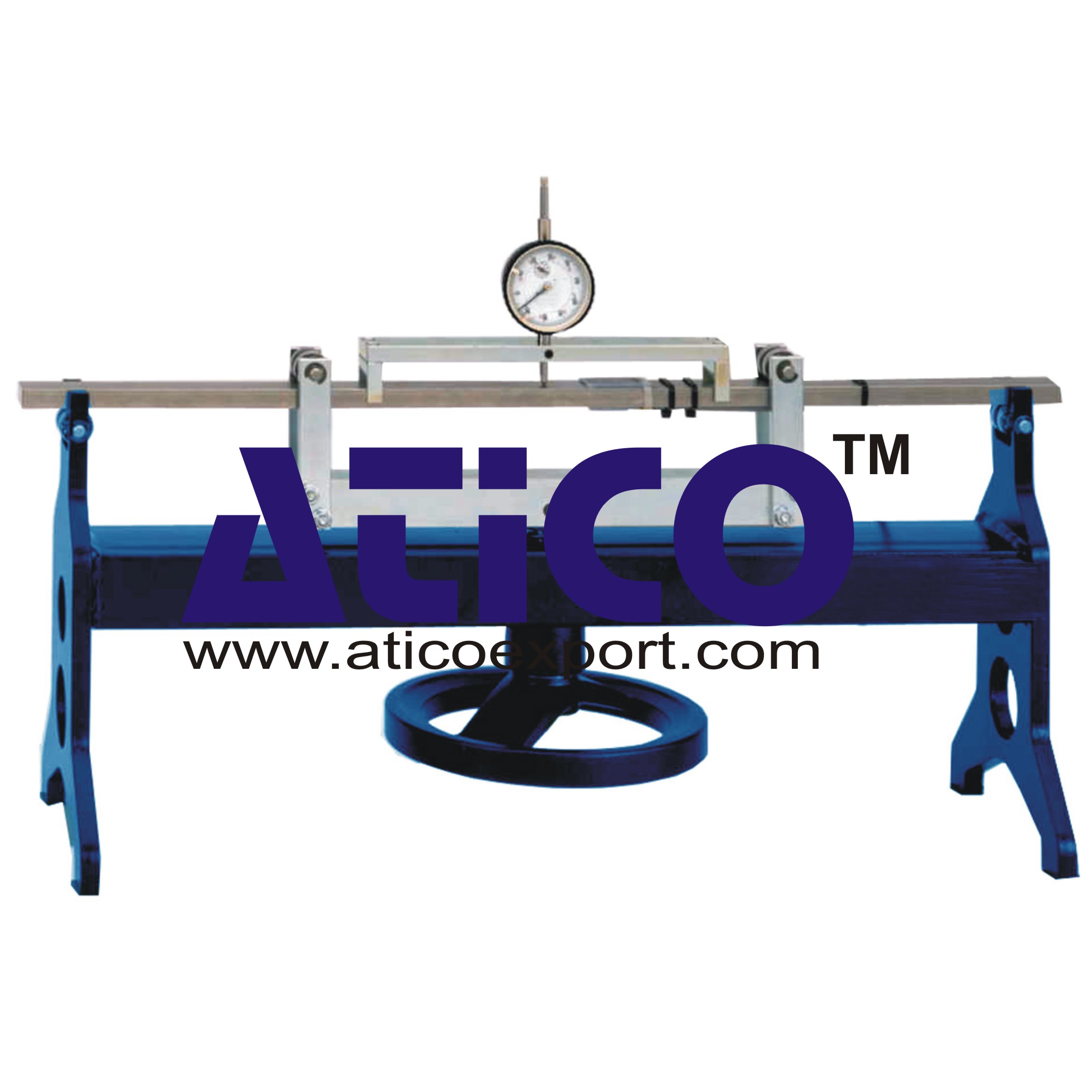
As universal aids to experimental stress and strain analysis, strain gauges enable mechanical strain to be converted into electrical signals. The signal obtained is processed by a strain measurement amplifier to give a display of the resulting strain. It is expected that the quantity measured by a measuring device and the readout subsequently indicated are identical. Consequently, the planning and evaluation of measurements makes allowance for the sensitivity to elongation (gauge factor) of strain gauges. A key character value of strain gauges – the gauge factor – indicates the correlation between the strain and the change in resistance. The experimental unit is used to measure deformation by means of a dial gauge and at the same time to measure strain by means of four strain gauges in full bridge configuration. The gauge factor of the strain gauges is then calculated arithmetically from the measurements. In the experiment, a bar is mounted on ball bearings at two points, thereby permitting purely bending stress to be applied. The bar is placed under load by means of a spindle and the resulting deflection is recorded by a dial gauge. As a result, the deformation can be read-off directly. At the same time the strain on the surface of the bar is recorded by two strain gauges on the compression side and two on the tension side. An adapter cable permits an external voltage source and measuring instrument to be connected, so the measurement bridge can be evaluated directly. The unknown gauge factor, as a key characteristic, can then be calculated from the deflection ascertained by the strain gauge measurements. Practical fundamentals, such as gauge application and configuration t0 form a measurement bridge, can be easily integrated into the overall teaching concept.
Specification:
1. Investigation of deflection and strain to determine gauge factor 2. Bending bar with 2 strain gauges on the compression side and tension side respectively 3. Strain gauge configured as full bridge 4. 2-point ball bearing mounting of bar permits purely bending load application 5. Mechanical load application device with spindle, handwheel and cross-arm 6. Dial gauge with adjustable dial for direct measurement of deflection 7. Adapter cable for connection to voltage source and to a measuring instrumentTechnical Data:
-Bending bar made of steel: 660x25x12mm
Strain gauge application
- full bridge, 350 Ohm - 2 strain gauges on the top and underside of the bar respectively Dial gauge: 0...20mm, graduations: 0,01mm Adapter cable with 4 laboratory plug connectors, 4mm
quick overview :
Determining Gauge Factor of Strain Gauges
Technical Description:
As universal aids to experimental stress and strain analysis, strain gauges enable mechanical strain to be converted into electrical signals. The signal obtained is processed by a strain measurement amplifier to give a display of the resulting strain. It is expected that the quantity measured by a measuring device and the readout subsequently indicated are identical. Consequently, the planning and evaluation of measurements makes allowance for the sensitivity to elongation (gauge factor) of strain gauges. A key character value of strain gauges – the gauge factor – indicates the correlation between the strain and the change in resistance. The experimental unit is used to measure deformation by means of a dial gauge and at the same time to measure strain by means of four strain gauges in full bridge configuration. The gauge factor of the strain gauges is then calculated arithmetically from the measurements. In the experiment, a bar is mounted on ball bearings at two points, thereby permitting purely bending stress to be applied. The bar is placed under load by means of a spindle and the resulting deflection is recorded by a dial gauge. As a result, the deformation can be read-off directly. At the same time the strain on the surface of the bar is recorded by two strain gauges on the compression side and two on the tension side. An adapter cable permits an external voltage source and measuring instrument to be connected, so the measurement bridge can be evaluated directly. The unknown gauge factor, as a key characteristic, can then be calculated from the deflection ascertained by the strain gauge measurements. Practical fundamentals, such as gauge application and configuration t0 form a measurement bridge, can be easily integrated into the overall teaching concept.
Specification:
1. Investigation of deflection and strain to determine gauge factor 2. Bending bar with 2 strain gauges on the compression side and tension side respectively 3. Strain gauge configured as full bridge 4. 2-point ball bearing mounting of bar permits purely bending load application 5. Mechanical load application device with spindle, handwheel and cross-arm 6. Dial gauge with adjustable dial for direct measurement of deflection 7. Adapter cable for connection to voltage source and to a measuring instrumentTechnical Data:
-Bending bar made of steel: 660x25x12mm
Strain gauge application
- full bridge, 350 Ohm - 2 strain gauges on the top and underside of the bar respectively Dial gauge: 0...20mm, graduations: 0,01mm Adapter cable with 4 laboratory plug connectors, 4mm
Product
Reviews
add Review
reviews
No Review Yet.
Copyrights © 2025 All Rights Reserved by Atico


Product
Reviews
add Review
reviews
No Review Yet.