Forces in a Howe Truss
Categories:Forces in a Howe Truss Technical Description : As light-weight structures offering a high degree of rigidity, trusses are employed in the construction of halls, bridges, cranes, pylons and masts. Tru...


Product
Description
Forces in a Howe Truss
Technical Description :
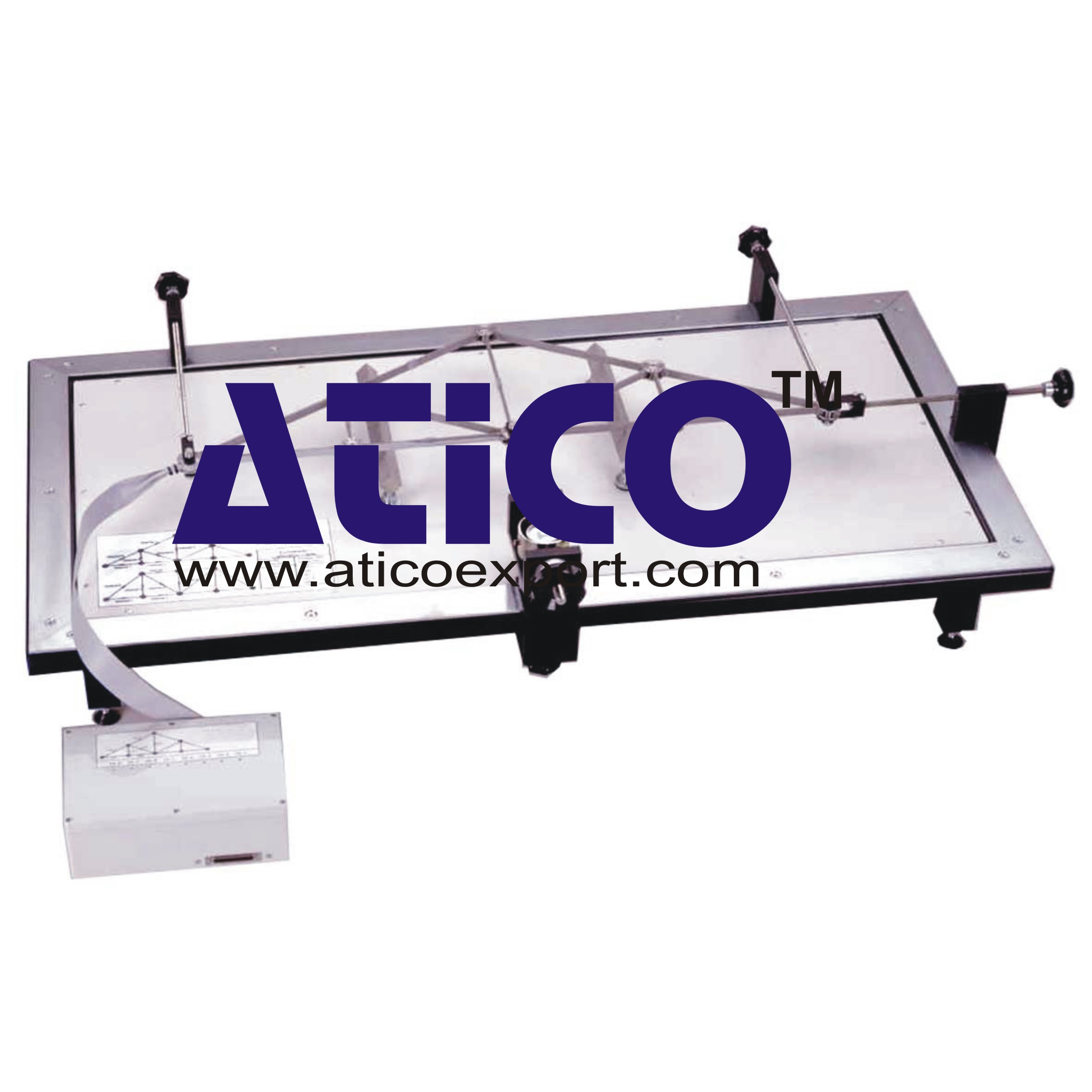
As light-weight structures offering a high degree of rigidity, trusses are employed in the construction of halls, bridges, cranes, pylons and masts. Trusses are bar structures in which the bars are subjected to compression or tension loading, but not to bending. The setup provides experiments on single plane trusses with a high degree of measurement accuracy and computerised result readout based on software. The ready assembled truss is mounted horizontally on a frame. The bars are joined by a “hinged” connection, using node discs. Consequently, our truss can be considered as an ideal truss. The external force is generated with the aid of a threaded spindle. The force can be applied in various directions and at various points. The forces occurring on the truss bars are recorded by strain gauges. All strain gauge measuring points are housed together in a connection box.The software is used to manage the measurement data and provide graphical representation of the bar forces. The software features a comprehensive help function. An additional truss is available to extend the scope of the experiment: Warren type. The well-structured instructional material sets out the fundamentals and provides a step-by-step guide through the experiments.
Specification:
1. Investigation of bar forces in a single plane, statically determinate truss 2. Ready assembled Howe truss 3. Frame for horizontal experiment setup 4. Any straight and inclined load cases possible 5. Fine adjustment of load force 6. Low-friction knife-edge bearing 7. 2 bearings for vertical forces, 1 bearing for horizontal forces 8. Pre-balanced strain gauge connection box with connection to measurement amplifierTechnical Data
Truss: Howe type
- bar cross-section: 10x3mm, stainless steel - bar lengths: 115,5, 200, 231mm - external loading: max. 600N - bars: 13, of which 7 with strain gauge full bridges
Load application device with force gauge
- tensile force: max. 2kN - stroke: 30mm Node discs: 8 Angle between bars: 30°, 45°
quick overview :
Forces in a Howe Truss
Technical Description :
As light-weight structures offering a high degree of rigidity, trusses are employed in the construction of halls, bridges, cranes, pylons and masts. Trusses are bar structures in which the bars are subjected to compression or tension loading, but not to bending. The setup provides experiments on single plane trusses with a high degree of measurement accuracy and computerised result readout based on software. The ready assembled truss is mounted horizontally on a frame. The bars are joined by a “hinged” connection, using node discs. Consequently, our truss can be considered as an ideal truss. The external force is generated with the aid of a threaded spindle. The force can be applied in various directions and at various points. The forces occurring on the truss bars are recorded by strain gauges. All strain gauge measuring points are housed together in a connection box.The software is used to manage the measurement data and provide graphical representation of the bar forces. The software features a comprehensive help function. An additional truss is available to extend the scope of the experiment: Warren type. The well-structured instructional material sets out the fundamentals and provides a step-by-step guide through the experiments.
Specification:
1. Investigation of bar forces in a single plane, statically determinate truss 2. Ready assembled Howe truss 3. Frame for horizontal experiment setup 4. Any straight and inclined load cases possible 5. Fine adjustment of load force 6. Low-friction knife-edge bearing 7. 2 bearings for vertical forces, 1 bearing for horizontal forces 8. Pre-balanced strain gauge connection box with connection to measurement amplifierTechnical Data
Truss: Howe type
- bar cross-section: 10x3mm, stainless steel - bar lengths: 115,5, 200, 231mm - external loading: max. 600N - bars: 13, of which 7 with strain gauge full bridges
Load application device with force gauge
- tensile force: max. 2kN - stroke: 30mm Node discs: 8 Angle between bars: 30°, 45°
Product
Reviews
add Review
reviews
No Review Yet.
Related
Products
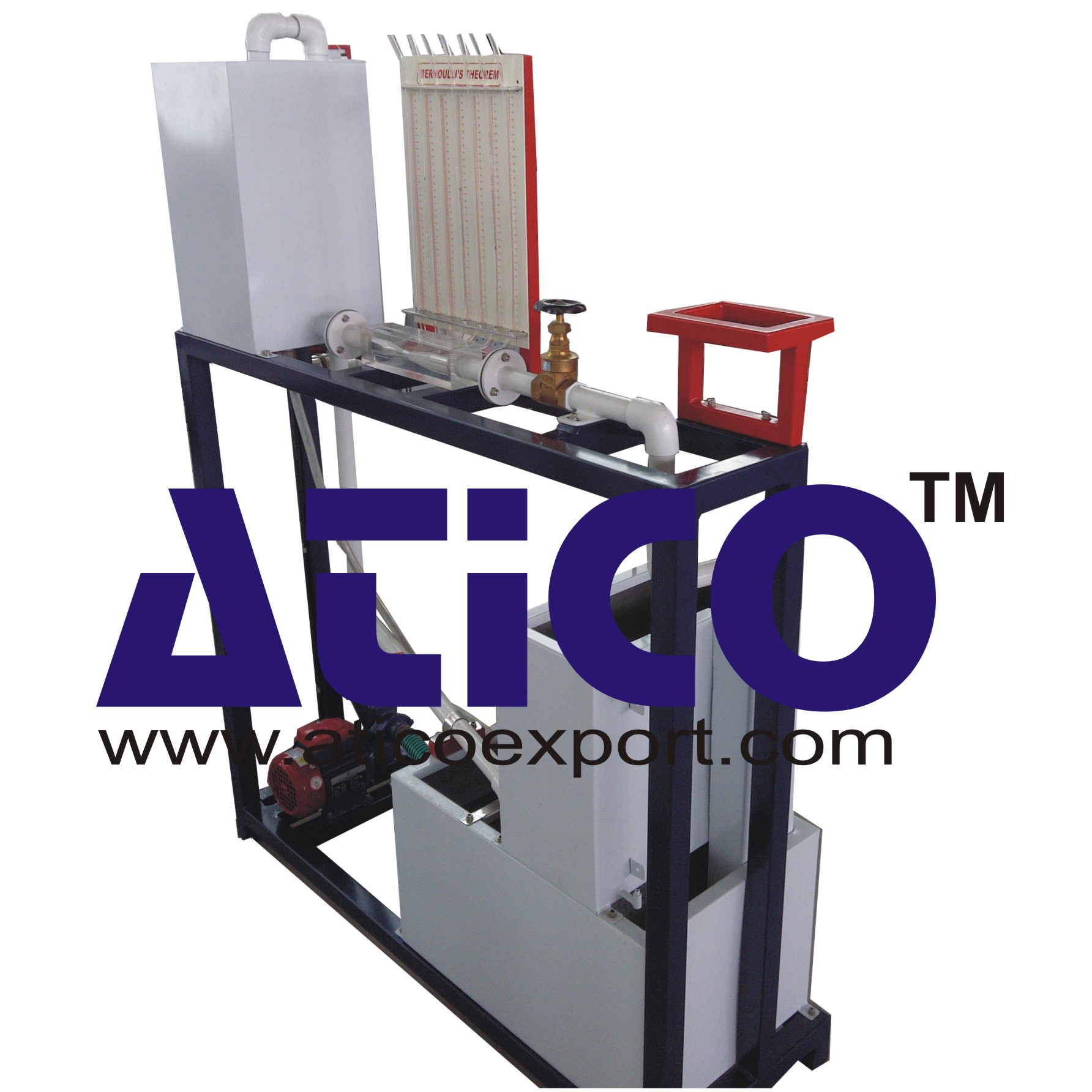
The apparatus consists of converging diverging circular tes...
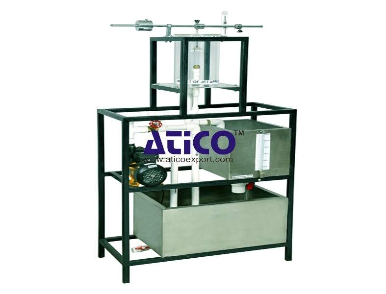
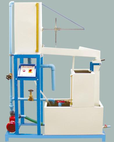
Impact Of Jet Apparatus It can measure the force generated b...
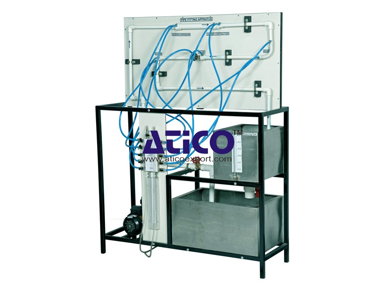
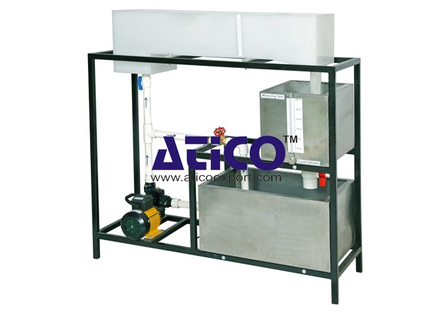
Losses In Pipe To determine minor flow losses(Fittings) in...
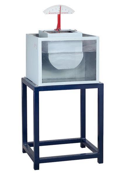
Metacentric Top Equipment Fundamentals of Buoyancy, Metacent...
Notch and Weir Apparatus Notches or Weirs are kept in the p...
Orifice and Mouthpiece Apparatus
Orifice and Mouthpiece Apparatus Both orifices and mouthpiec...
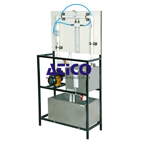
Orifice Meter This equipment is designed to introduce colle...
Pipe Friction Equipment Main Losses In Pipe (Losses Due To...
Product
Reviews
add Review
reviews
No Review Yet.