Francis Turbine
Categories:Francis Turbine The Francis Turbine was invented by James B. Francis in Lowell, Massachusetts. It is an inward-flow reaction turbine, which is the type of Water Turbine. It performs its operations in...
Product
Description
Francis Turbine
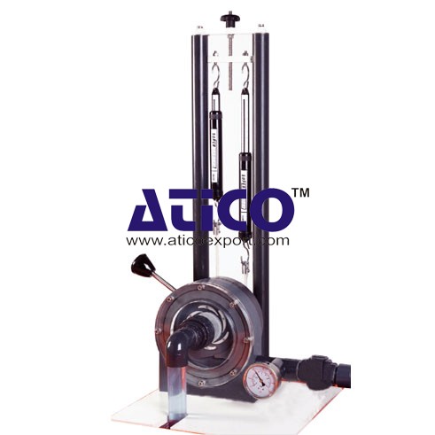
The Francis Turbine was invented by James B. Francis in Lowell, Massachusetts. It is an inward-flow reaction turbine, which is the type of Water Turbine. It performs its operations in a water head from 40 to 600 m. This turbine is specially used for the production of electrical power. Net dimensions and weight (assembled): 400 mm x 360 mm x 700 mm and 11 kg The turbine has a sturdy base which sits on the top of the hydraulic bench. The turbine connects to the pumped supply of the hydraulic bench. The bench measures the flow rate. A mechanical gauge at the inlet connection of the turbine measures the inlet pressure. Adjustable guide vanes in the turbine alter the flow rate and direction of flow to the impeller (runner) of the turbine. The end of the turbine outlet tube(draft) is in the open-water channel of the hydraulic bench. Included with the turbine is a weir plate to create a shallow reservoir in the water channel of the bench. This ensures that water covers the end of the draft during tests. A band brake with spring balances measures the torque at the turbine shaft. To know more about Fluid Mechanics Lab Equipment, visit back to main page of Fluid Mechanics.quick overview :
Francis Turbine
The Francis Turbine was invented by James B. Francis in Lowell, Massachusetts. It is an inward-flow reaction turbine, which is the type of Water Turbine. It performs its operations in a water head from 40 to 600 m. This turbine is specially used for the production of electrical power. Net dimensions and weight (assembled): 400 mm x 360 mm x 700 mm and 11 kg The turbine has a sturdy base which sits on the top of the hydraulic bench. The turbine connects to the pumped supply of the hydraulic bench. The bench measures the flow rate. A mechanical gauge at the inlet connection of the turbine measures the inlet pressure. Adjustable guide vanes in the turbine alter the flow rate and direction of flow to the impeller (runner) of the turbine. The end of the turbine outlet tube(draft) is in the open-water channel of the hydraulic bench. Included with the turbine is a weir plate to create a shallow reservoir in the water channel of the bench. This ensures that water covers the end of the draft during tests. A band brake with spring balances measures the torque at the turbine shaft. To know more about Fluid Mechanics Lab Equipment, visit back to main page of Fluid Mechanics.Product
Reviews
add Review
reviews
No Review Yet.
Copyrights © 2025 All Rights Reserved by Atico








Product
Reviews
add Review
reviews
No Review Yet.