Frequency Modulation & Demodulation
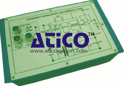
Categories: Educational TrainersExperimental training board has been designed specifically for the study of frequency modulation and demodulation. Practical experience on this board carries great educative value for science and engi...
Product
Description
Experimental training board has been designed specifically for the study of frequency modulation and demodulation. Practical experience on this board carries great educative value for science and engineering students.Object:
- To observe the effect of D.C. voltage on frequency of carrier waveform
- To frequency modulate the carrier with Audio signal, observe F.M. waveform on C.R.O., and measure its modulation index
- To demodulate the F.M. singal and observe the output on C.R.O.
- To plot the characteristics curve of the slope detector demodulating circuit
- ± 12V D.C. at 100 mA, IC Regulated Power Supply
- Carrier generator circuit which generates the carrier signal
- Audio frequency modulating signal
- Variable D.C. is provided to see the frequency deviation in carrier frequency
- Frequency Modulation circuit with buffer stage at the output
- Demodulating circuit
- Adequate no. of other electronic components
- Mains ON/OFF switch, Fuse and Jewel light
- The unit is operative on 230V ±10% at 50Hz A.C. Mains
- Adequate no. of patch cords stackable from rear both ends 4mm spring loaded plug length ½ metre
- Good Quality, reliable terminal/sockets are provided at appropriate places on panel for connections & observation of waveforms
- Strongly supported by detailed Operating Instructions, giving details of Object, Theory, Design procedures, Report Suggestions and Book References
- Weight : 3 Kg. (Approx.)
- Dimension : W 340 x H 110 x D 210
quick overview :
Experimental training board has been designed specifically for the study of frequency modulation and demodulation. Practical experience on this board carries great educative value for science and engineering students.Object:
- To observe the effect of D.C. voltage on frequency of carrier waveform
- To frequency modulate the carrier with Audio signal, observe F.M. waveform on C.R.O., and measure its modulation index
- To demodulate the F.M. singal and observe the output on C.R.O.
- To plot the characteristics curve of the slope detector demodulating circuit
- ± 12V D.C. at 100 mA, IC Regulated Power Supply
- Carrier generator circuit which generates the carrier signal
- Audio frequency modulating signal
- Variable D.C. is provided to see the frequency deviation in carrier frequency
- Frequency Modulation circuit with buffer stage at the output
- Demodulating circuit
- Adequate no. of other electronic components
- Mains ON/OFF switch, Fuse and Jewel light
- The unit is operative on 230V ±10% at 50Hz A.C. Mains
- Adequate no. of patch cords stackable from rear both ends 4mm spring loaded plug length ½ metre
- Good Quality, reliable terminal/sockets are provided at appropriate places on panel for connections & observation of waveforms
- Strongly supported by detailed Operating Instructions, giving details of Object, Theory, Design procedures, Report Suggestions and Book References
- Weight : 3 Kg. (Approx.)
- Dimension : W 340 x H 110 x D 210
Product
Reviews
add Review
reviews
No Review Yet.
Copyrights © 2025 All Rights Reserved by Atico





Product
Reviews
add Review
reviews
No Review Yet.