Motorized Tail Empennage System
Categories: Mechanical Lab Equipment ManufacturerMotorized Tail Empennage System Teaching objectives of Motorized Tail Empennage System This system allows to do practical works in Mechanical and electrical engineering : Structural analysis of t...


Product
Description
Motorized Tail Empennage System
Teaching objectives of Motorized Tail Empennage System- This system allows to do practical works in Mechanical and electrical engineering :
- Structural analysis of the tail empennage control mechanism
- Function of the tail empennage in the flight dynamics of the A320 plane
- Functional analysis of the tail empennage control mechanism
- Identification of the components of tail empennage control mechanism
- Schematic and geometric representations of this mechanism
- Kinematic’s behaviour of this mechanism
- Static’s behaviour of this mechanism
- Technical analysis, feature of the assemblies and guiding,
- Definition, structure of a controlled system and definition of the performances
- Functioning in opened loop of the system with drawing of the graphs of the kinematics and dynamics functions
- Functioning in Closed loop of the system controlled ( proportional setting) with drawing of the graphs of the kinematics and dynamics functions
Technical specifications
- A mechanical system :
- A tail empennage support articulated according to the frame,
- Possibility to create manually, a complementary disturbance strength on the tail empennage.
- A direct current motor
- A pair of conical gearings, with right gear teeth (ratio ½)
- A ball screw – nut system, step : 2 mm
- Two spring pots of 12.1 N/mm (simulating the aerodynamic forces),
- A control and data acquisition system :
- A PCI data acquisition card “National Instrument “
- A dedicated software designed on "Labview "
- An angular position sensor mounted on the ball screw system
- A potentiometer sensor situated on the swivelling case, measuring the rotation angle of the tail empennage,
- Data acquisition of the following parameters: voltage of the motor, moment of the motor torque, angular positions of the motor shaft and of the tail empennage, angular velocities of the input and output of the mechanism, global reduction gearing ratio,
- A power control card driving the step-by-step motor , a power supply, the connexion cable to link the cabinet to the PC computer via the data acquisition card.
- A visualization device for the functioning of the ball screw
- Technical manual in English with practical works and CAD files on CD-ROM
Essential requirements
- A PC computer with Windows®, SolidWorks® and Cosmosmotion® softwares.
- Power supply : 220V - 50 Hz – Single phase.
- Dimensions (L x W x H) : 700 x 500 x 400 mm - Weight : 4 kg.
- Electric cabinet (L x W x H) : 300 x 220 x 150 mm - Weight : 1 kg.
quick overview :
Motorized Tail Empennage System
Teaching objectives of Motorized Tail Empennage System- This system allows to do practical works in Mechanical and electrical engineering :
- Structural analysis of the tail empennage control mechanism
- Function of the tail empennage in the flight dynamics of the A320 plane
- Functional analysis of the tail empennage control mechanism
- Identification of the components of tail empennage control mechanism
- Schematic and geometric representations of this mechanism
- Kinematic’s behaviour of this mechanism
- Static’s behaviour of this mechanism
- Technical analysis, feature of the assemblies and guiding,
- Definition, structure of a controlled system and definition of the performances
- Functioning in opened loop of the system with drawing of the graphs of the kinematics and dynamics functions
- Functioning in Closed loop of the system controlled ( proportional setting) with drawing of the graphs of the kinematics and dynamics functions
Technical specifications
- A mechanical system :
- A tail empennage support articulated according to the frame,
- Possibility to create manually, a complementary disturbance strength on the tail empennage.
- A direct current motor
- A pair of conical gearings, with right gear teeth (ratio ½)
- A ball screw – nut system, step : 2 mm
- Two spring pots of 12.1 N/mm (simulating the aerodynamic forces),
- A control and data acquisition system :
- A PCI data acquisition card “National Instrument “
- A dedicated software designed on "Labview "
- An angular position sensor mounted on the ball screw system
- A potentiometer sensor situated on the swivelling case, measuring the rotation angle of the tail empennage,
- Data acquisition of the following parameters: voltage of the motor, moment of the motor torque, angular positions of the motor shaft and of the tail empennage, angular velocities of the input and output of the mechanism, global reduction gearing ratio,
- A power control card driving the step-by-step motor , a power supply, the connexion cable to link the cabinet to the PC computer via the data acquisition card.
- A visualization device for the functioning of the ball screw
- Technical manual in English with practical works and CAD files on CD-ROM
Essential requirements
- A PC computer with Windows®, SolidWorks® and Cosmosmotion® softwares.
- Power supply : 220V - 50 Hz – Single phase.
- Dimensions (L x W x H) : 700 x 500 x 400 mm - Weight : 4 kg.
- Electric cabinet (L x W x H) : 300 x 220 x 150 mm - Weight : 1 kg.
Product
Reviews
add Review
reviews
No Review Yet.
Related
Products
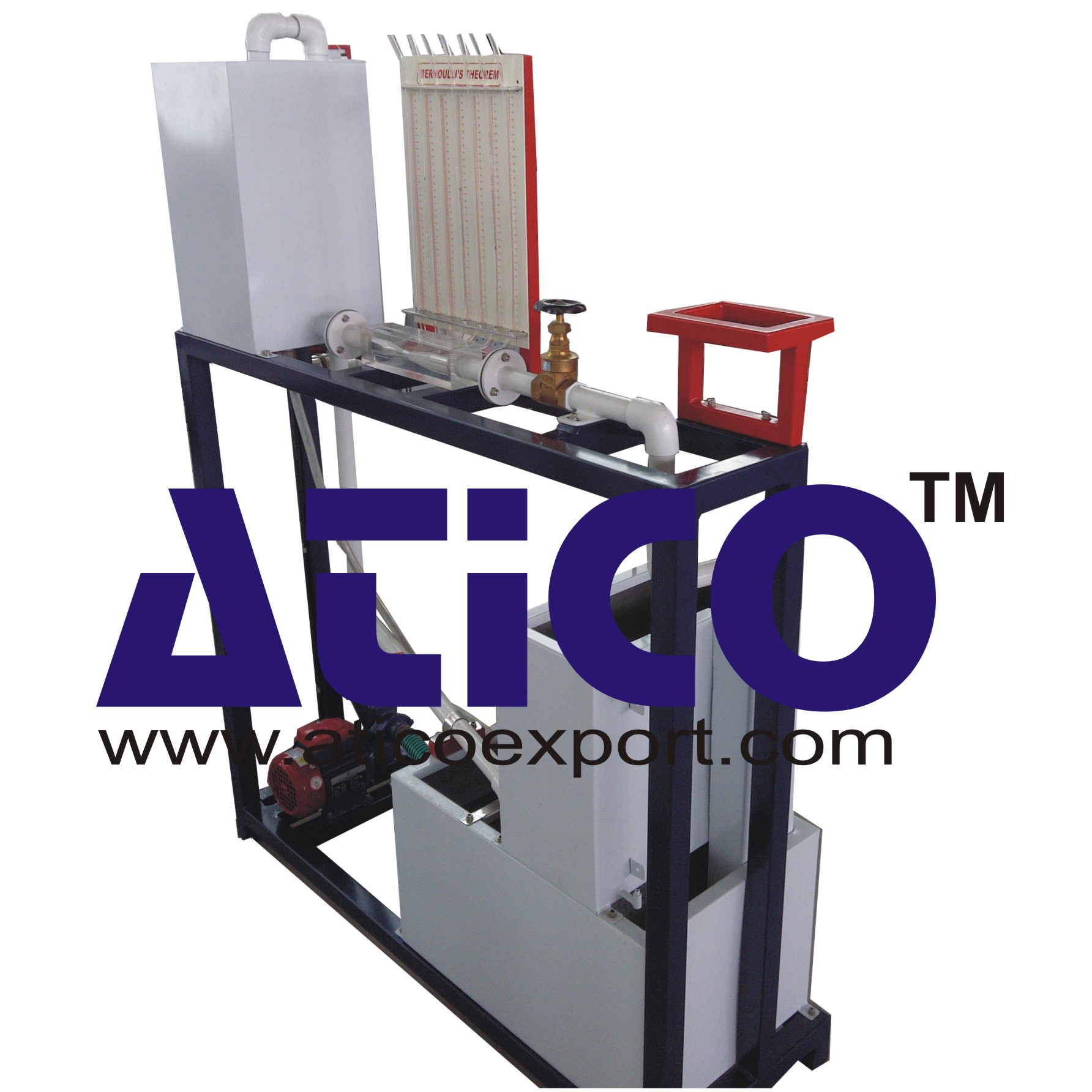
The apparatus consists of converging diverging circular tes...
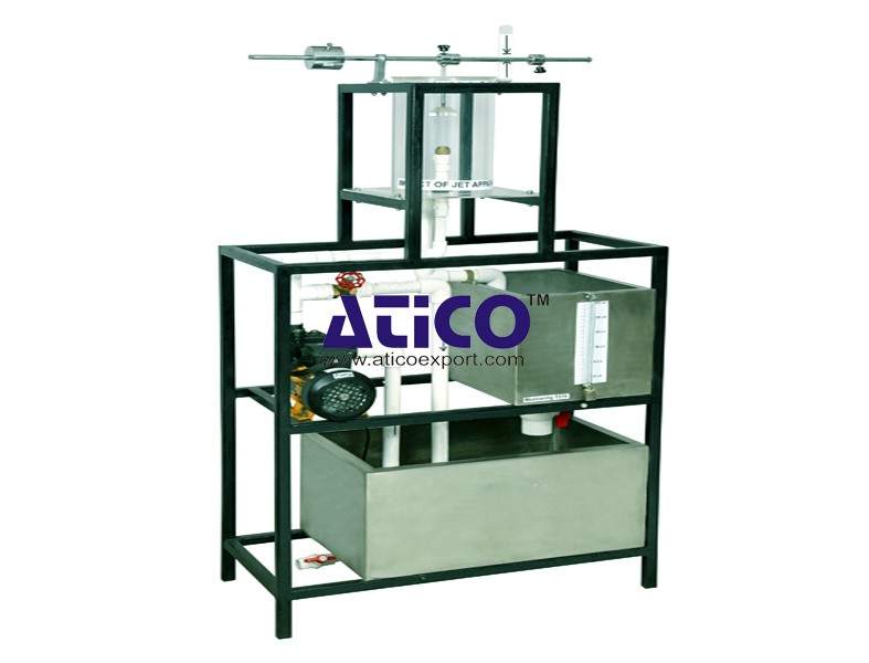
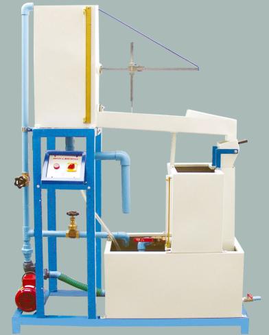
Impact Of Jet Apparatus It can measure the force generated b...
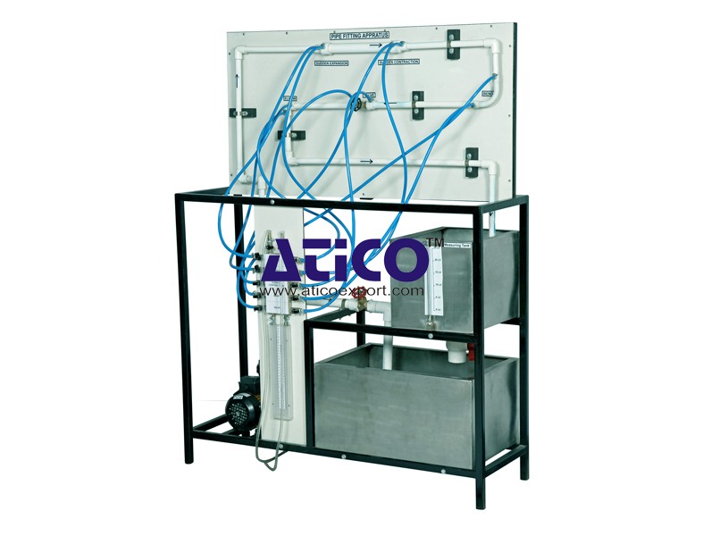
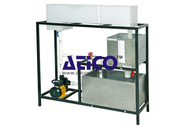
Losses In Pipe To determine minor flow losses(Fittings) in...
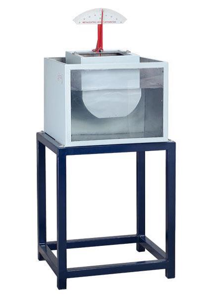
Metacentric Top Equipment Fundamentals of Buoyancy, Metacent...
Notch and Weir Apparatus Notches or Weirs are kept in the p...
Orifice and Mouthpiece Apparatus
Orifice and Mouthpiece Apparatus Both orifices and mouthpiec...
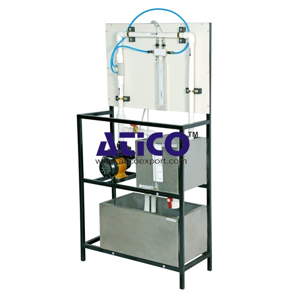
Orifice Meter This equipment is designed to introduce colle...
Pipe Friction Equipment Main Losses In Pipe (Losses Due To...
Product
Reviews
add Review
reviews
No Review Yet.