Pelton Wheel Turbine Test Rig
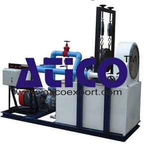
Categories:Pelton Wheel Turbine Test Rig The present set-up consists of a runner. The buckets are mounted on the runner. The water is fed to the turbine, through SS nozzle with a SS spear, by means of Centrifuga...
Product
Description
Pelton Wheel Turbine Test Rig
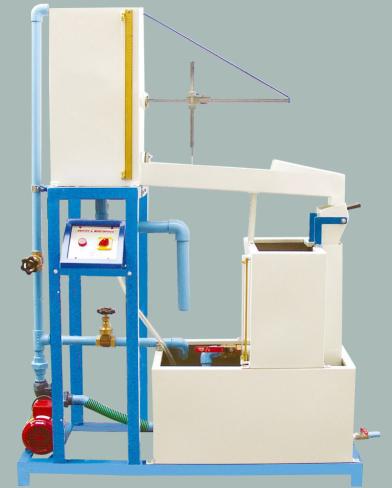
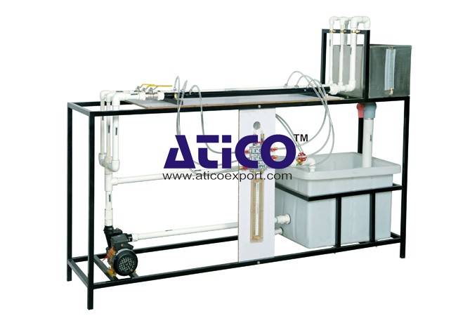
The present set-up consists of a runner. The buckets are mounted on the runner. The water is fed to the turbine, through SS nozzle with a SS spear, by means of Centrifugal Pump, tangentially to the runner. Row of water into turbine is regulated by adjusting the spear position by the help of a given hand wheel The runner is directly mounted on one end of a central SS shaft and other end is connected to a brake arrangement. The circular window of the turbine casing is provided with a transparent acrylic sheet for observation of flow on to the buckets. This runner assembly is supported by rigid MS structure. Load is applied to the turbine with the help of this brake dynamometer so that the efficiency of the turbine can be calculated. Pressure gauge is fitted at the inlet of the turbine to measure the total supply head to the turbine
Experiment:
- To study the operation of a Pelton Wheel Turbine
- To determine the Output Power of Pelton Wheel Turbine
- To determine the Turbine Efficiency
Utilities Required:
- Water Supply and Drain
- Electricity 1.5 kW, 440V AC, Three Phase
- Floor Area 1.5 x 0.75 m
quick overview :
Pelton Wheel Turbine Test Rig
The present set-up consists of a runner. The buckets are mounted on the runner. The water is fed to the turbine, through SS nozzle with a SS spear, by means of Centrifugal Pump, tangentially to the runner. Row of water into turbine is regulated by adjusting the spear position by the help of a given hand wheel The runner is directly mounted on one end of a central SS shaft and other end is connected to a brake arrangement. The circular window of the turbine casing is provided with a transparent acrylic sheet for observation of flow on to the buckets. This runner assembly is supported by rigid MS structure. Load is applied to the turbine with the help of this brake dynamometer so that the efficiency of the turbine can be calculated. Pressure gauge is fitted at the inlet of the turbine to measure the total supply head to the turbine
Experiment:
- To study the operation of a Pelton Wheel Turbine
- To determine the Output Power of Pelton Wheel Turbine
- To determine the Turbine Efficiency
Utilities Required:
- Water Supply and Drain
- Electricity 1.5 kW, 440V AC, Three Phase
- Floor Area 1.5 x 0.75 m
Product
Reviews
add Review
reviews
No Review Yet.
Copyrights © 2025 All Rights Reserved by Atico



Product
Reviews
add Review
reviews
No Review Yet.