Photovoltaic Solar Energy Unit
Categories:Description: The Photovoltaic Solar Energy Unit includes equipment that uses the photo-conversion law for the direct conversion of solar radiation into electricity. The absorbed energy is provided by...
Product
Description
Description:
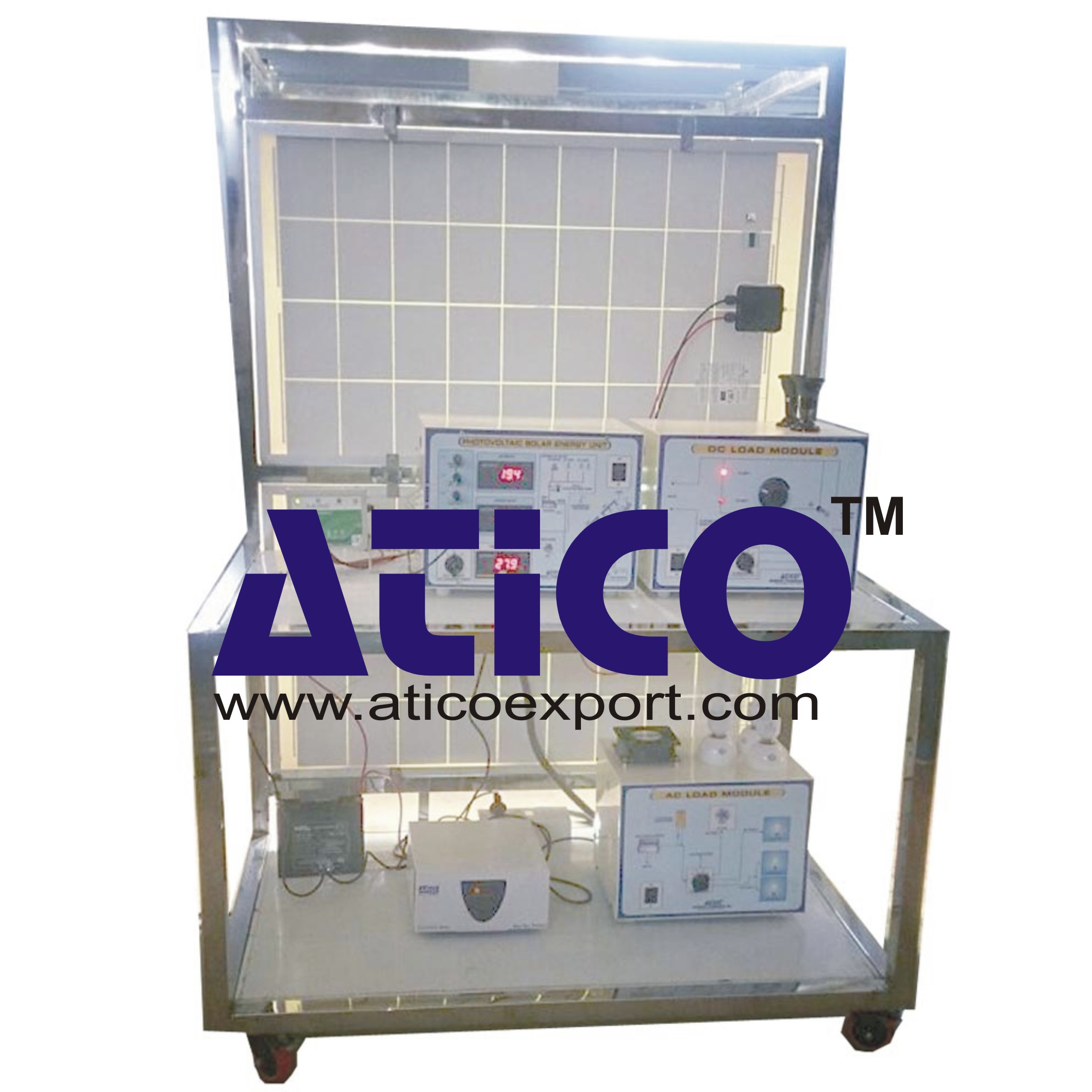
The Photovoltaic Solar Energy Unit includes equipment that uses the photo-conversion law for the direct conversion of solar radiation into electricity. The absorbed energy is provided by simulated solar radiation, which in our case is supplied by a panel with powerful light sources (solar lamps).The unit contains:
- Photovoltaic solar panels.
- Solar simulator composed of solar lamps.
- Ventilation system.
- DC load and battery charger regulator.
- Auxiliary battery charger.
- Battery.
- DC loads module.
- Sensors (temperature, light radiation, DC current and DC voltage).
- Electronic console.
Optional (NOT included in the standard supply):
Kit of Conversion and Consumption Simulation (AC):
- Single-phase inverter.
- AC Loads Module:
- 3 Lamps
- 1 axial compact fan with plastic guards
- 4 positions selector.
- AC Voltage and current sensors.
Grid Connection Inverter Kit:
- Grid Connection Inverter.
- Grid simulator (ESR).
Specification
This unit for the study of the conversion of solar energy into electric energy. Anodized aluminum structure and panels in painted steel. Diagram on the front panel with similar distribution to the elements in the real unit. This unit includes wheels for its mobility.The unit includes:
Two photovoltaic solar panels (polycrystalline):
- Tempered glass modules with high level of transmissivity.
- Encapsulating material: modified ethylene-vinyl acetate.
- Output nominal power: 66W. 2 Area of the panel: 0.51 m .
- Max. current: 3.76 A. Max. voltage: 17.53 V.
- 36 cells, 156 x156 mm each.
Solar simulator composed of:
- Aluminum frame.
- 8 Halogen lamps of 400W each one, distributed into two independent voltage regulated circuits.
- Electrically safe.
Ventilation system that allows to analyze the temperature influence on the unit operation, formed by:
- 4 Axial compact fans with plastic guards.
DC load and battery charger regulator:
- It regulates how power generated in the photovoltaic solar panels is distributed to and from the auxiliary battery and to the load. A display informs about the state of the charge, operating parameters and fault messages. The functions of the electronic protection are:
- Overvoltage disconnection, short circuit protection of load and module, overvoltage protection at module input, over-temperature and overload protection, and battery overvoltage shutdown.
Auxiliary battery charger:
- It carefully assesses the battery and then delivers the optimum charge required.
Battery:
- Nominal voltage: 12V. Rated capacity (20 hours rate): 24A/H.
DC loads module:
- Metallic box with diagram on the front panel.
- 2 Lamps of 24V.
- One DC motor: voltage: 36V, power: 5W.
- Rheostat of 500W.
- Solar panels work at open-circuit.
- Rheostat and lamps are connected directly to the solar panels. These loads can be connected individually or in parallel with the aid of manual switches.
- The DC motor is directly connected to the solar panels.
- The DC load is disconnected and the solar panels are directly connected to the charge regulator
quick overview :
Description:
The Photovoltaic Solar Energy Unit includes equipment that uses the photo-conversion law for the direct conversion of solar radiation into electricity. The absorbed energy is provided by simulated solar radiation, which in our case is supplied by a panel with powerful light sources (solar lamps).The unit contains:
- Photovoltaic solar panels.
- Solar simulator composed of solar lamps.
- Ventilation system.
- DC load and battery charger regulator.
- Auxiliary battery charger.
- Battery.
- DC loads module.
- Sensors (temperature, light radiation, DC current and DC voltage).
- Electronic console.
Optional (NOT included in the standard supply):
Kit of Conversion and Consumption Simulation (AC):
- Single-phase inverter.
- AC Loads Module:
- 3 Lamps
- 1 axial compact fan with plastic guards
- 4 positions selector.
- AC Voltage and current sensors.
Grid Connection Inverter Kit:
- Grid Connection Inverter.
- Grid simulator (ESR).
Specification
This unit for the study of the conversion of solar energy into electric energy. Anodized aluminum structure and panels in painted steel. Diagram on the front panel with similar distribution to the elements in the real unit. This unit includes wheels for its mobility.The unit includes:
Two photovoltaic solar panels (polycrystalline):
- Tempered glass modules with high level of transmissivity.
- Encapsulating material: modified ethylene-vinyl acetate.
- Output nominal power: 66W. 2 Area of the panel: 0.51 m .
- Max. current: 3.76 A. Max. voltage: 17.53 V.
- 36 cells, 156 x156 mm each.
Solar simulator composed of:
- Aluminum frame.
- 8 Halogen lamps of 400W each one, distributed into two independent voltage regulated circuits.
- Electrically safe.
Ventilation system that allows to analyze the temperature influence on the unit operation, formed by:
- 4 Axial compact fans with plastic guards.
DC load and battery charger regulator:
- It regulates how power generated in the photovoltaic solar panels is distributed to and from the auxiliary battery and to the load. A display informs about the state of the charge, operating parameters and fault messages. The functions of the electronic protection are:
- Overvoltage disconnection, short circuit protection of load and module, overvoltage protection at module input, over-temperature and overload protection, and battery overvoltage shutdown.
Auxiliary battery charger:
- It carefully assesses the battery and then delivers the optimum charge required.
Battery:
- Nominal voltage: 12V. Rated capacity (20 hours rate): 24A/H.
DC loads module:
- Metallic box with diagram on the front panel.
- 2 Lamps of 24V.
- One DC motor: voltage: 36V, power: 5W.
- Rheostat of 500W.
- Solar panels work at open-circuit.
- Rheostat and lamps are connected directly to the solar panels. These loads can be connected individually or in parallel with the aid of manual switches.
- The DC motor is directly connected to the solar panels.
- The DC load is disconnected and the solar panels are directly connected to the charge regulator
Product
Reviews
add Review
reviews
No Review Yet.
Copyrights © 2025 All Rights Reserved by Atico



Product
Reviews
add Review
reviews
No Review Yet.