System Of Horizontal Travel Lifting
Categories: Mechanical Lab Equipment ManufacturerSystem Of Horizontal Travel Lifting General presentation Coming from applications of lifting industry, this System Of Horizontal Travel Lifting functions in order to transfer of a modular load, whos...


Product
Description
System Of Horizontal Travel Lifting
General presentation
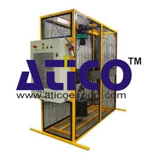
Coming from applications of lifting industry, this System Of Horizontal Travel Lifting functions in order to transfer of a modular load, whose values are understood between 50 to 125 daN. Intended to be a part of the systems used in electrotechnics lab, this system has been designed to make wire by students different types of asynchronous motor starting as well as a logic control. It is built around an electrical hoist with a capacity of 125 kg associated with an electrical cabinet integrated to the whole. It answers the securities norms in force.
Teaching objectives
- Mono speed asynchronous motor starting.
- Bi-speed asynchronous motor starting.
- Variation of frequency of the asynchronous motor.
- Logic control of the brake in lifting mode, safety management.
- Control of measurable sizes of the installation: absence or presence of voltage (system able to be used for the electric security clearance).
- Commissioning and inspection of the good running after wiring realization.
- Maintenance and control of the system (thermal relay, control of the travels ends).
Technical Specifications of System Of Horizontal Travel Lifting
Structure:- Mechanically welded Frame.
- Working area protected by a wire fencing.
- Access to the load by a door (with closing electric contact and key locking) located on the frame.
- Lifting motor: 850W, 400V three-phase, bi-speed.
- Horizontal travel motor: 400V three-phase, bi-speed.
- Lifting linear speed : 2 and 8 m/mn.
- Horizontal linear speed : 5 and 20 m/mn.
- 4 travel ends mechanics.
- Vertical axis: high and low.
- Load: 8 kg modular metallic masses with 11 additional elements of 10 kg, easily removable.
- The electrical cabinet is full part of the system. It receives the bearing plate wired by the student.
- It consists of two distinct zones:
- Area receiving receives the bearing plate wired by the student.
- A fastener device and connectors allows a quick assembly of the bearing plate wired by the student.
- The buttons and indicators are fixed on the door and are connected to the bearing plate by a fast connector.
This second area concerns the power supply of the electrical cabinet. It is already wired and the student doesn't have an access to it. It includes:
- An alternative 24V power supply.
- A 3*400V+N+T power supply protected by a 30 mA differential circuit-breaker.
- One security logical building block.
- One security limit switch on the door that conditions the power sequencing of the bearing plate. This security can be inhibited permitting to make measurement exercises or electric authorization.
- The power sequencing buttons and lights.
- A main switch.
- An electric power supply by three phased normalized connector 3*400V+N+T 16A.
- Lot of material to wire version direct starting on the 2 axes.
- Lot of material to wire version speed driver.
General features of the system:
- Measurements: length: 2440 mm, width of the basis: 620 mm, height 1630 mm.
- Weight: 300 Kg.
- Electric power supplied : 3 x 400 V+T+N - 16 A.
Feature of the confinement casket:
- Dimensions (L x w x h) out all: 320 x 650 x 1000 mm.
- Dimensions of the wiring zone: width: 600 mm, height: 800 mm.
quick overview :
System Of Horizontal Travel Lifting
General presentation
Coming from applications of lifting industry, this System Of Horizontal Travel Lifting functions in order to transfer of a modular load, whose values are understood between 50 to 125 daN. Intended to be a part of the systems used in electrotechnics lab, this system has been designed to make wire by students different types of asynchronous motor starting as well as a logic control. It is built around an electrical hoist with a capacity of 125 kg associated with an electrical cabinet integrated to the whole. It answers the securities norms in force.
Teaching objectives
- Mono speed asynchronous motor starting.
- Bi-speed asynchronous motor starting.
- Variation of frequency of the asynchronous motor.
- Logic control of the brake in lifting mode, safety management.
- Control of measurable sizes of the installation: absence or presence of voltage (system able to be used for the electric security clearance).
- Commissioning and inspection of the good running after wiring realization.
- Maintenance and control of the system (thermal relay, control of the travels ends).
Technical Specifications of System Of Horizontal Travel Lifting
Structure:- Mechanically welded Frame.
- Working area protected by a wire fencing.
- Access to the load by a door (with closing electric contact and key locking) located on the frame.
- Lifting motor: 850W, 400V three-phase, bi-speed.
- Horizontal travel motor: 400V three-phase, bi-speed.
- Lifting linear speed : 2 and 8 m/mn.
- Horizontal linear speed : 5 and 20 m/mn.
- 4 travel ends mechanics.
- Vertical axis: high and low.
- Load: 8 kg modular metallic masses with 11 additional elements of 10 kg, easily removable.
- The electrical cabinet is full part of the system. It receives the bearing plate wired by the student.
- It consists of two distinct zones:
- Area receiving receives the bearing plate wired by the student.
- A fastener device and connectors allows a quick assembly of the bearing plate wired by the student.
- The buttons and indicators are fixed on the door and are connected to the bearing plate by a fast connector.
This second area concerns the power supply of the electrical cabinet. It is already wired and the student doesn't have an access to it. It includes:
- An alternative 24V power supply.
- A 3*400V+N+T power supply protected by a 30 mA differential circuit-breaker.
- One security logical building block.
- One security limit switch on the door that conditions the power sequencing of the bearing plate. This security can be inhibited permitting to make measurement exercises or electric authorization.
- The power sequencing buttons and lights.
- A main switch.
- An electric power supply by three phased normalized connector 3*400V+N+T 16A.
- Lot of material to wire version direct starting on the 2 axes.
- Lot of material to wire version speed driver.
General features of the system:
- Measurements: length: 2440 mm, width of the basis: 620 mm, height 1630 mm.
- Weight: 300 Kg.
- Electric power supplied : 3 x 400 V+T+N - 16 A.
Feature of the confinement casket:
- Dimensions (L x w x h) out all: 320 x 650 x 1000 mm.
- Dimensions of the wiring zone: width: 600 mm, height: 800 mm.
Product
Reviews
add Review
reviews
No Review Yet.
Related
Products
The apparatus consists of converging diverging circular te...
Impact Of Jet Apparatus It can measure the force generated...
Losses In Pipe To determine minor flow losses(Fittings) i...
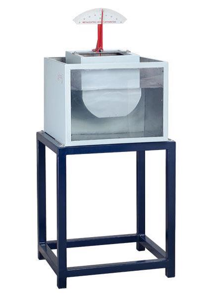
Metacentric Top Equipment Fundamentals of Buoyancy, Metacen...
Notch and Weir Apparatus Notches or Weirs are kept in the...
Orifice and Mouthpiece Apparatus
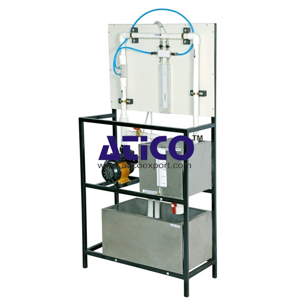
Orifice and Mouthpiece Apparatus Both orifices and mouthpie...
Orifice Meter This equipment is designed to introduce col...
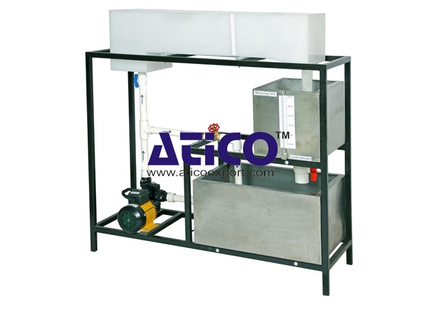
Pipe Friction Equipment Main Losses In Pipe (Losses Due T...
Copyrights © 2019 All Rights Reserved by Atico
Product
Reviews
add Review
reviews
No Review Yet.