- Admin
- 0 Comments
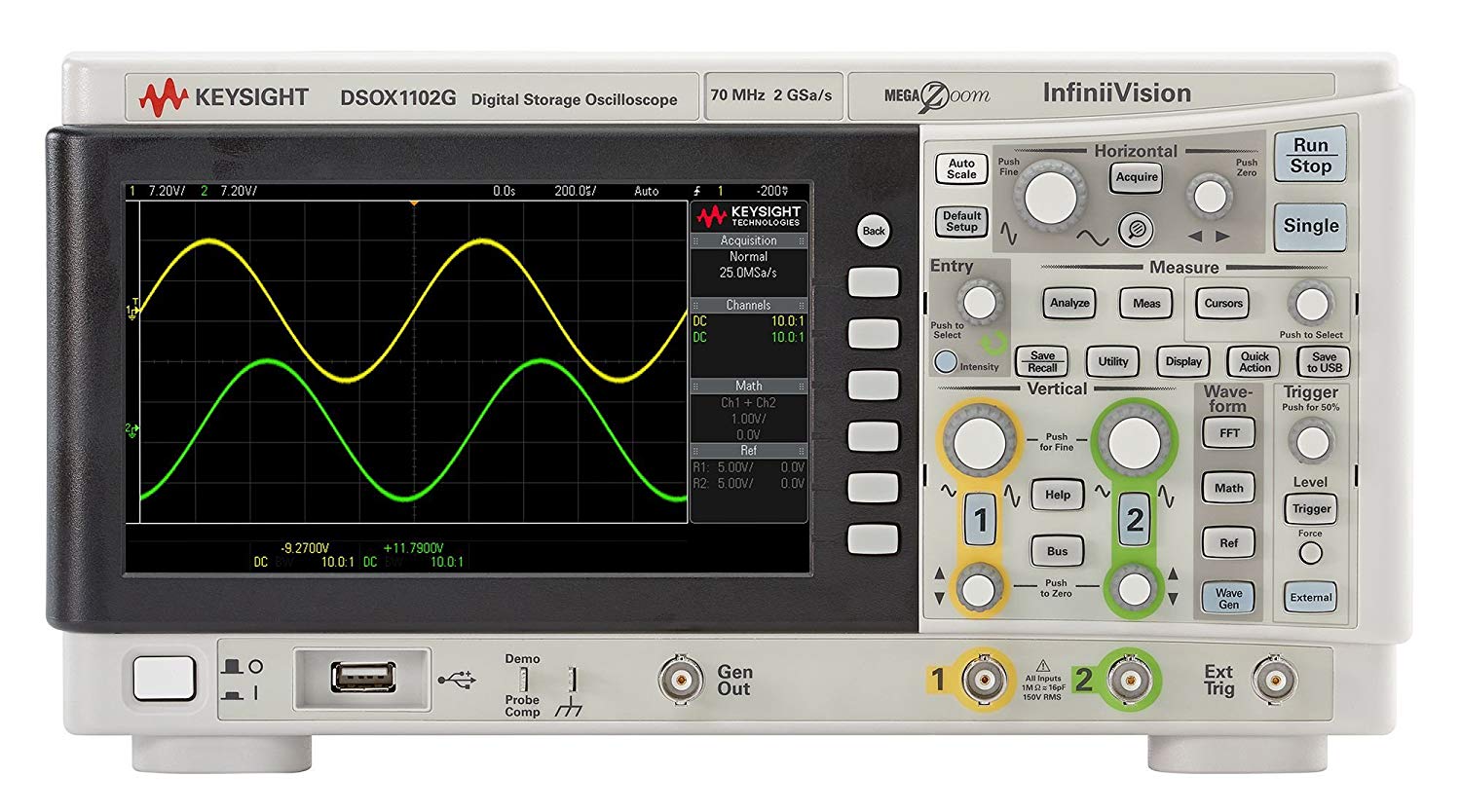
Oscilloscope is called the Stethoscope of Electrical Engineering for a reason, it is an electronic Laboratory Testing Equipment that displays the value of an electric signal over time. Its display shows the amplitude of a signal on the y-axis and the time along the x-axis.
They are commonly used for the: -
Measure the shape of a Waveform that is the graph of a voltage.
Measure amplitude and the frequency of a signal.
Detect the noise in the signal.
Voltage of the input channel is read by the Digital Storage Oscilloscopes (DSO), the signal is then amplified, conditioned and finally converted with the help of the ADC that is the Analog to Digital Converter. These samples of voltage are then stored in the Scopes memory and displayed on the screen.
Atico Exports is your go-to in order to get quality stethoscopes for your Electric Engineering purposes. All Electrical Training Equipment is ISO Certified.
Digital Storage Oscilloscope essentials: -
Dual-channel - channel bandwidth: 70MHz ~ 300MHz
The volume is exquisite and it is convenient to carry.
Use Colored TFT LCD, the waveform display is clearer and stable
The real-time sampling rate is 2G Sa/s
Memory depth is 24k Trigger Modes: Edge, Pulse, Video, Slope, Alternative and Delay trigger modes
Front and Back USB Host/Device, GPIB
Unique Digital Filter function and Waveform recorder function
Waveform recorder function
Pass/Fail function
Thirty-two parameters Auto measure function
Cursor measure covers Manual mode, Track mode, and Auto mode
Channel waveform and it's FFT waveform display on split-screen
Pop-up Menu display pattern is more convenient for users using it.
Multiple Language User Interface
Support multilingual online help
Essential Electrical Training Instruments and controls of the DSO are as follows: -
Display; it will show the status of the signal
Division; the screen is divided into a grid containing X-axis and Y-axis that shows Time in seconds and Charge in Volts respectively. The so-called Graticule is the reference for the value of the signal on the screen.
Analog Input Channels; these input channels are located on the front of the unit, the inner conductor carries the signals and the outer one connects it to the common grounds.
Analog Probes; can be connected to any of the input channels on the front of the scope. They have a BNC connection on one of its ends and the probe tip on the other end.
Horizontal Scale Controls; this knob adjusts the time per division of the scope. By turning the knob counterclockwise it increases the time per division and the clockwise turning will decrease the time per division of the scope.
Vertical Scale Controls; this knob adjusts the volts per division of the scope. By turning the knob counterclockwise it increases the volts per division and the clockwise turning will decrease the volts per division of the scope.
Horizontal Position Control; This captures the Horizontal position that has been displayed, this, in turn, allows multiple parts of the signal to be displayed.
Vertical Position Control; This captures the Vertical position that has been displayed, this, in turn, allows multiple parts of the signal to be displayed.
Trigger Control; allows the selection and configuration of the trigger and the associated display option.
Vernier Dials; this allows the knobs to have dual functionality.
You can buy the Digital Storage Oscilloscope of different storage capacities with ATICO Export.


