Bending Test Plastic Deformation
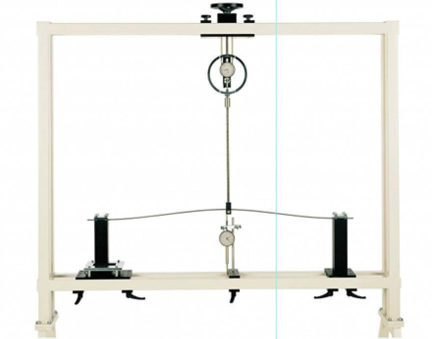
Categories: Engineering Lab EquipmentMechanical stress, to which design elements are generally exposed, generates stresses in the affected component or the material. If these stresses are too large, there is plastic deformation of the ma...
Product
Description
Mechanical stress, to which design elements are generally
exposed, generates stresses in the affected component or the material. If these
stresses are too large, there is plastic deformation of the material in
addition to the elastic, reversible deformation. The component does not return
fully to its original form after the deformation, resulting in a change of
shape. The beam studied in is mounted on both sides. A movable and a fixed
support are included in the scope of delivery to secure the beam. The beam is
loaded with a point load. The load application device can be positioned
anywhere on the frame. A dial gauge records the deformation. Beams of different
materials and profiles are included in the scope of delivery.
Learning Objectives/Experiments
Load on a beam with a point load
Plot a load–extension diagram and determine the nonlinear
behaviour
Compare the load and relief curves
Demonstrate the invalidity of the superposition principle in
the plastic region
Features
Observe and determine the transition from elastic to plastic
deformation
Plot load–extension diagrams
Specification
Study a beam until plastic deformation
Load on the beam from point load
Fixed and movable support for supporting the beam
Beams of different materials and profiles
Dial gauge for recording the deformation
Storage system for parts
Experimental setup in the mounting frame
Technical Data
Beams
1x 1000x15x3mm, steel
1x 1000x15x3mm, aluminium
1x H-profile, 1000x15x15x2mm, aluminium
Load application device
max. load: ±5000N
max. travel: 100mm
Measuring ranges
travel: 0…50mm
LxWxH: 1170x480x178mm
Weight: approx. 30kg
quick overview :
Mechanical stress, to which design elements are generally
exposed, generates stresses in the affected component or the material. If these
stresses are too large, there is plastic deformation of the material in
addition to the elastic, reversible deformation. The component does not return
fully to its original form after the deformation, resulting in a change of
shape. The beam studied in is mounted on both sides. A movable and a fixed
support are included in the scope of delivery to secure the beam. The beam is
loaded with a point load. The load application device can be positioned
anywhere on the frame. A dial gauge records the deformation. Beams of different
materials and profiles are included in the scope of delivery.
Learning Objectives/Experiments
Load on a beam with a point load
Plot a load–extension diagram and determine the nonlinear
behaviour
Compare the load and relief curves
Demonstrate the invalidity of the superposition principle in
the plastic region
Features
Observe and determine the transition from elastic to plastic
deformation
Plot load–extension diagrams
Specification
Study a beam until plastic deformation
Load on the beam from point load
Fixed and movable support for supporting the beam
Beams of different materials and profiles
Dial gauge for recording the deformation
Storage system for parts
Experimental setup in the mounting frame
Technical Data
Beams
1x 1000x15x3mm, steel
1x 1000x15x3mm, aluminium
1x H-profile, 1000x15x15x2mm, aluminium
Load application device
max. load: ±5000N
max. travel: 100mm
Measuring ranges
travel: 0…50mm
LxWxH: 1170x480x178mm
Weight: approx. 30kg
Product
Reviews
add Review
reviews
No Review Yet.
Copyrights © 2025 All Rights Reserved by Atico




Product
Reviews
add Review
reviews
No Review Yet.