Capacity Control and Faults In Refrigeration Systems
Categories: Engineering Lab EquipmentThe efficient control of the capacity and temperature in refrigeration systems is an important topic in refrigeration technology. With different methods of capacity control can be investigated. The c...


Product
Description
The efficient control of the capacity and temperature in
refrigeration systems is an important topic in refrigeration technology. With
different methods of capacity control can be investigated.
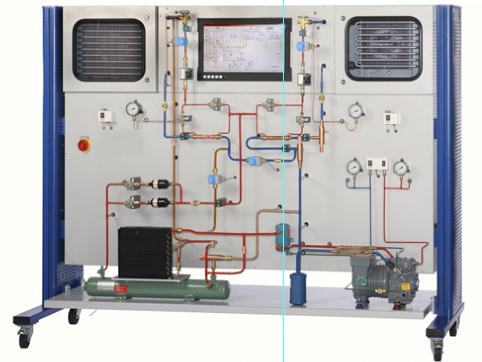
The components of a refrigeration circuit with refrigeration
and freezing chambers are arranged clearly in the trainer. Solenoid valves
enable the separate or parallel operation of the evaporators in the two
chambers. The circuit is equipped with a capacity controller, a start-up
controller and a combined pressures switch for the delivery and intake sides of
the compressor. One heat exchanger each in the inlet of the two evaporators
enables the supercooling of the refrigerant to be investigated for the
efficiency of the process. The refrigeration capacity of the two individual
chambers is controlled by a thermostat. The refrigeration chamber also features
an evaporation pressure controller.
Learning Objectives/Experiments
Familiarisation with the key devices for changing the
refrigeration capacity
Thermostat
Capacity controller
Start-up controller
Evaporation pressure controller
Condensation pressure controller
Fault finding in refrigeration system components
Effect of refrigerant supercooling
Familiarisation with defrosting methods
Electric defrost heater
Hot gas defrosting
Representation of the thermodynamic cycle in the log p-h
diagram
Specification
Investigation of a refrigeration system with refrigeration
and freezing chambers
Refrigeration circuit with compressor, condenser, capacity
controller, start-up controller, combined pressure switch and 2 evaporators in
insulated chambers
Each chamber with solenoid valve, thermostat, thermostatic
expansion valve, fan and heat exchanger for refrigerant supercooling
Refrigeration chamber with evaporation pressure controller
Freezing chamber with electric defrost heater and hot gas
defrosting
Separate or parallel operation of the chambers via solenoid
valves
Simulation of 12 faults
Touch panel PC for fault activation, data acquisition,
evaluation and representation in the log p-h diagram
Technical Data
Compressor
refrigeration capacity: 1640W at -10/50°C
power consumption: 980W at -10/50°C
Condenser with fan
volumetric air flow rate: 570m3/h
Evaporator transfer areas
refrigeration chamber: 1,12m2
freezing chamber: 1,88m2
Electric defrost heater: approx. 125W
Capacity controller: 0,2…6bar
Start-up controller: 0,2…6bar
Thermostat: 2x -25…15°C
Evaporation pressure controller: 0…5,5bar
Refrigerant
R449A
GWP: 1397
filling volume: 3,21kg
CO2-equivalent: 4,5t
Measuring ranges
temperature: 6x -50…50°C; 5x 0…100°C
pressure: 3x -1…15bar; 2x -1…24bar
flow rate: 2x 2…29L/h
power consumption: 0…5kW (compressor)
400V, 50Hz, 3 phases
230V, 60Hz, 3 phases; 400V, 60Hz, 3 phases
quick overview :
The efficient control of the capacity and temperature in
refrigeration systems is an important topic in refrigeration technology. With
different methods of capacity control can be investigated.
The components of a refrigeration circuit with refrigeration
and freezing chambers are arranged clearly in the trainer. Solenoid valves
enable the separate or parallel operation of the evaporators in the two
chambers. The circuit is equipped with a capacity controller, a start-up
controller and a combined pressures switch for the delivery and intake sides of
the compressor. One heat exchanger each in the inlet of the two evaporators
enables the supercooling of the refrigerant to be investigated for the
efficiency of the process. The refrigeration capacity of the two individual
chambers is controlled by a thermostat. The refrigeration chamber also features
an evaporation pressure controller.
Learning Objectives/Experiments
Familiarisation with the key devices for changing the
refrigeration capacity
Thermostat
Capacity controller
Start-up controller
Evaporation pressure controller
Condensation pressure controller
Fault finding in refrigeration system components
Effect of refrigerant supercooling
Familiarisation with defrosting methods
Electric defrost heater
Hot gas defrosting
Representation of the thermodynamic cycle in the log p-h
diagram
Specification
Investigation of a refrigeration system with refrigeration
and freezing chambers
Refrigeration circuit with compressor, condenser, capacity
controller, start-up controller, combined pressure switch and 2 evaporators in
insulated chambers
Each chamber with solenoid valve, thermostat, thermostatic
expansion valve, fan and heat exchanger for refrigerant supercooling
Refrigeration chamber with evaporation pressure controller
Freezing chamber with electric defrost heater and hot gas
defrosting
Separate or parallel operation of the chambers via solenoid
valves
Simulation of 12 faults
Touch panel PC for fault activation, data acquisition,
evaluation and representation in the log p-h diagram
Technical Data
Compressor
refrigeration capacity: 1640W at -10/50°C
power consumption: 980W at -10/50°C
Condenser with fan
volumetric air flow rate: 570m3/h
Evaporator transfer areas
refrigeration chamber: 1,12m2
freezing chamber: 1,88m2
Electric defrost heater: approx. 125W
Capacity controller: 0,2…6bar
Start-up controller: 0,2…6bar
Thermostat: 2x -25…15°C
Evaporation pressure controller: 0…5,5bar
Refrigerant
R449A
GWP: 1397
filling volume: 3,21kg
CO2-equivalent: 4,5t
Measuring ranges
temperature: 6x -50…50°C; 5x 0…100°C
pressure: 3x -1…15bar; 2x -1…24bar
flow rate: 2x 2…29L/h
power consumption: 0…5kW (compressor)
400V, 50Hz, 3 phases
230V, 60Hz, 3 phases; 400V, 60Hz, 3 phases
Product
Reviews
add Review
reviews
No Review Yet.
Related
Products
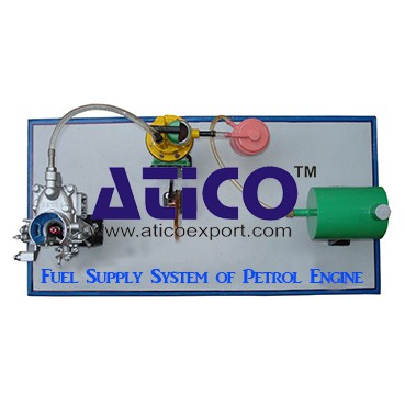
Fuel Supply System Of Petrol Engine
Fuel Supply System Of Petrol EngineFuel is supplied under pr...
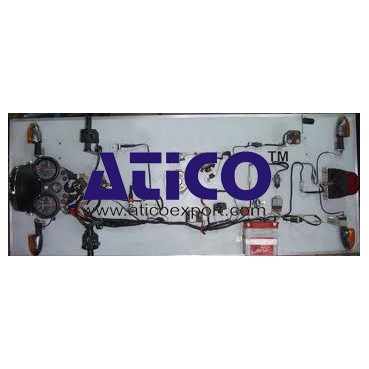
It is an open type instructional apparatus with second hand...
Distributor is connected to camshaft and cam shaft is connec...
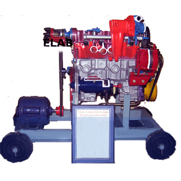
The device is consisting of the front able with wheel &b...
Specification: 1. Experimental setup to demonstrate simple...
Technical Description: Supplementary set extends the scope...
Equilibrium Single Plane, Statically Det...
Equilibrium in a Single Plane, Statically Determinate S...
Equilibrium Of Moments On Pulleys
Equilibrium Of Moments On Pulleys Manufacturer and Supplier...
Product
Reviews
add Review
reviews
No Review Yet.