Compression Refrigeration System
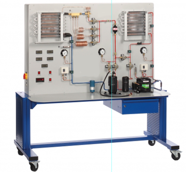
Categories: Engineering Lab EquipmentThe setup of represents a typical refrigeration circuit consisting of a hermetic compressor, condenser, evaporator and expansion element. Evaporator and condenser are designed as finned tube heat exch...
Product
Description
The setup of represents a typical refrigeration circuit
consisting of a hermetic compressor, condenser, evaporator and expansion
element. Evaporator and condenser are designed as finned tube heat exchangers.
The pipes of both heat exchangers are partially transparent to visualise the
process of the phase transition during evaporation and condensing. Three
capillary tubes of different lengths and a thermostatic expansion valve can be
compared as expansion elements. The trainer is equipped with a receiver for
refrigerant. Using the receiver, refrigerant can be added to or removed from
the refrigeration circuit. This allows for the effects of overfilling or
underfilling of the system to be examined.
Learning Objectives/Experiments
Function and operational behaviour of the refrigeration
circuit components
Operation with expansion valve or with capillary tubes of
different lengths
Underfilling or overfilling with refrigerant
Thermodynamic cycle in the log p-h diagram
From the log p-h diagram and in comparison with the measured
values
Determination of the refrigeration capacity
Determination of the coefficient of performance
Determination of the efficiency of the compressor
Features
Compression refrigeration system with transparent evaporator
and transparent condenser
Comparison of different expansion elements
Effect of under/overfilling of the system with refrigerant
Specification
Investigation of a refrigeration system with different
expansion elements
Refrigeration circuit consisting of a hermetic compressor,
condenser, evaporator and expansion element
Transparent finned tube heat exchangers as condenser and
evaporator to observe the phase transitions of the refrigerant
Expansion valve and capillary tubes of different lengths as
expansion elements
Receiver for underfilling/overfilling the system with
refrigerant
Sensors record pressure and temperature
Refrigerant mass flow rate calculated in the software from
recorded measured values
Compressor equipped with two pressure switches
Technical Data
Compressor
power consumption: 288W at 7,2°/54,4°C
refrigeration capacity: 463W at 7,2/54,4°C
Condenser and evaporator with fan
max. volumetric air flow rate condenser: 300m3/h
max. volumetric air flow rate evaporator: 180m3/h
Capillary tubes: 1,5m, 3m, 6m
Receiver for refrigerant: 1,3L
Refrigerant
R513A
GWP: 631
filling volume: 2,5kg
CO2-equivalent: 1,6t
Measuring ranges
pressure: -1…9bar / -1…24bar
temperature: 4x -40…150°C, 1x -100…100°C
flow rate: 2…18m3/h
power consumption: 0…1000W
230V, 50Hz, 1 phase
230V, 60Hz, 1 phase
120V, 60Hz, 1 phase
quick overview :
The setup of represents a typical refrigeration circuit
consisting of a hermetic compressor, condenser, evaporator and expansion
element. Evaporator and condenser are designed as finned tube heat exchangers.
The pipes of both heat exchangers are partially transparent to visualise the
process of the phase transition during evaporation and condensing. Three
capillary tubes of different lengths and a thermostatic expansion valve can be
compared as expansion elements. The trainer is equipped with a receiver for
refrigerant. Using the receiver, refrigerant can be added to or removed from
the refrigeration circuit. This allows for the effects of overfilling or
underfilling of the system to be examined.
Learning Objectives/Experiments
Function and operational behaviour of the refrigeration
circuit components
Operation with expansion valve or with capillary tubes of
different lengths
Underfilling or overfilling with refrigerant
Thermodynamic cycle in the log p-h diagram
From the log p-h diagram and in comparison with the measured
values
Determination of the refrigeration capacity
Determination of the coefficient of performance
Determination of the efficiency of the compressor
Features
Compression refrigeration system with transparent evaporator
and transparent condenser
Comparison of different expansion elements
Effect of under/overfilling of the system with refrigerant
Specification
Investigation of a refrigeration system with different
expansion elements
Refrigeration circuit consisting of a hermetic compressor,
condenser, evaporator and expansion element
Transparent finned tube heat exchangers as condenser and
evaporator to observe the phase transitions of the refrigerant
Expansion valve and capillary tubes of different lengths as
expansion elements
Receiver for underfilling/overfilling the system with
refrigerant
Sensors record pressure and temperature
Refrigerant mass flow rate calculated in the software from
recorded measured values
Compressor equipped with two pressure switches
Technical Data
Compressor
power consumption: 288W at 7,2°/54,4°C
refrigeration capacity: 463W at 7,2/54,4°C
Condenser and evaporator with fan
max. volumetric air flow rate condenser: 300m3/h
max. volumetric air flow rate evaporator: 180m3/h
Capillary tubes: 1,5m, 3m, 6m
Receiver for refrigerant: 1,3L
Refrigerant
R513A
GWP: 631
filling volume: 2,5kg
CO2-equivalent: 1,6t
Measuring ranges
pressure: -1…9bar / -1…24bar
temperature: 4x -40…150°C, 1x -100…100°C
flow rate: 2…18m3/h
power consumption: 0…1000W
230V, 50Hz, 1 phase
230V, 60Hz, 1 phase
120V, 60Hz, 1 phase
Product
Reviews
add Review
reviews
No Review Yet.
Copyrights © 2025 All Rights Reserved by Atico



Product
Reviews
add Review
reviews
No Review Yet.