Electrical Connection Of Refrigerant Compressors
Categories: Engineering Lab EquipmentThe wiring of electrical components for the start and operation of refrigerant compressors is a typical task in the field of refrigeration. Safety aspects also play an important role. With this knowle...


Product
Description
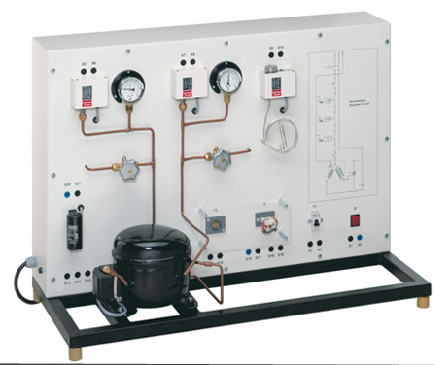
The wiring of electrical components for the start and
operation of refrigerant compressors is a typical task in the field of
refrigeration. Safety aspects also play an important role. With this knowledge
and these skills can be acquired. All components are operated and tested with
mains voltage to provide high relevance for practice. The electrical components
for the start and operation of the refrigerant compressor are arranged clearly
visible. The electrical connection of the individual components is made with
cables via the lab jacks. The components are e.g. the capacitor and start-up
relay necessary to start the motor. The circuit diagram on the front panel
enables the easy allocation of the individual components.
Learning Objectives/Experiments
Read, understand, wire and test electric circuit diagrams
for refrigerant compressors
Design and operation of electrical components of refrigerant
compressors
Start-up capacitor
Start-up relay
Overheat protection
Automatic fuse
Pressure switch
Thermostat
Design and testing of a safety chain
Representation methods in electrical engineering
Symbols
Circuit diagrams
Safety aspects when handling mains voltage
Specification
Experimental unit from the practical series for the training
of mechatronics engineers for refrigeration
Correct electrical connection of a refrigerant compressor
Refrigerant circuit with compressor, receiver, 2 valves and
2 manometers to investigate pressure switches on the delivery and intake sides
Electrical components for the start and operation of the
compressor mounted clearly visible
Lab jacks and cables to connect the electrical components
Operation of a thermostat
Circuit diagram on the front panel for easy identification
of the components
Technical Data
Refrigerant compressor
power consumption: approx. 193W at 5/55°C
refrigeration capacity: 374W at 5/55°C
Receiver: 0,8L
Manometer measuring ranges
delivery side: -1…24bar
intake side: -1…9bar
Pressure switch control range
delivery side: 8…32bar
intake side: -0,9…7bar
Thermostat: -5…35°C
Electrical components for the compressor
start-up capacitor
start-up relay
overheat protection (bimetallic)
automatic fuse
Refrigerant
R513A
GWP: 631
filling volume: 300g
CO2-equivalent: 0,2t
230V, 50Hz, 1 phase
230V, 60Hz, 1 phase; 120V, 60Hz, 1 phase
quick overview :
The wiring of electrical components for the start and
operation of refrigerant compressors is a typical task in the field of
refrigeration. Safety aspects also play an important role. With this knowledge
and these skills can be acquired. All components are operated and tested with
mains voltage to provide high relevance for practice. The electrical components
for the start and operation of the refrigerant compressor are arranged clearly
visible. The electrical connection of the individual components is made with
cables via the lab jacks. The components are e.g. the capacitor and start-up
relay necessary to start the motor. The circuit diagram on the front panel
enables the easy allocation of the individual components.
Learning Objectives/Experiments
Read, understand, wire and test electric circuit diagrams
for refrigerant compressors
Design and operation of electrical components of refrigerant
compressors
Start-up capacitor
Start-up relay
Overheat protection
Automatic fuse
Pressure switch
Thermostat
Design and testing of a safety chain
Representation methods in electrical engineering
Symbols
Circuit diagrams
Safety aspects when handling mains voltage
Specification
Experimental unit from the practical series for the training
of mechatronics engineers for refrigeration
Correct electrical connection of a refrigerant compressor
Refrigerant circuit with compressor, receiver, 2 valves and
2 manometers to investigate pressure switches on the delivery and intake sides
Electrical components for the start and operation of the
compressor mounted clearly visible
Lab jacks and cables to connect the electrical components
Operation of a thermostat
Circuit diagram on the front panel for easy identification
of the components
Technical Data
Refrigerant compressor
power consumption: approx. 193W at 5/55°C
refrigeration capacity: 374W at 5/55°C
Receiver: 0,8L
Manometer measuring ranges
delivery side: -1…24bar
intake side: -1…9bar
Pressure switch control range
delivery side: 8…32bar
intake side: -0,9…7bar
Thermostat: -5…35°C
Electrical components for the compressor
start-up capacitor
start-up relay
overheat protection (bimetallic)
automatic fuse
Refrigerant
R513A
GWP: 631
filling volume: 300g
CO2-equivalent: 0,2t
230V, 50Hz, 1 phase
230V, 60Hz, 1 phase; 120V, 60Hz, 1 phase
Product
Reviews
add Review
reviews
No Review Yet.
Related
Products
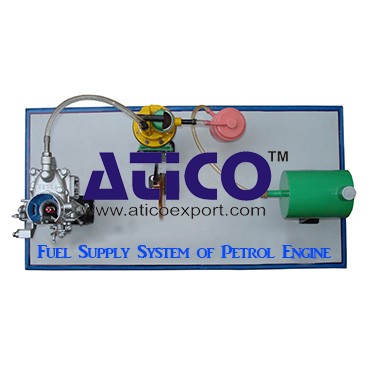
Fuel Supply System Of Petrol Engine
Fuel Supply System Of Petrol EngineFuel is supplied under pr...
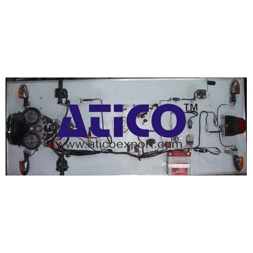
It is an open type instructional apparatus with second hand...
Distributor is connected to camshaft and cam shaft is connec...
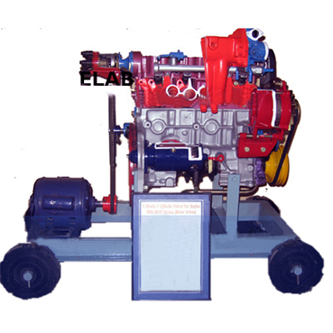
The device is consisting of the front able with wheel &b...
Specification: 1. Experimental setup to demonstrate simple...
Technical Description: Supplementary set extends the scope...
Equilibrium Single Plane, Statically Det...
Equilibrium in a Single Plane, Statically Determinate S...
Equilibrium Of Moments On Pulleys
Equilibrium Of Moments On Pulleys Manufacturer and Supplier...
Product
Reviews
add Review
reviews
No Review Yet.