Heat Pump For Cooling And Heating Operation
Categories: Engineering Lab EquipmentRefrigeration systems and heat pumps only differ in the definition of their use, but can be of the same design. For example, goods can be refrigerated in a supermarket and the store heated with the wa...


Product
Description
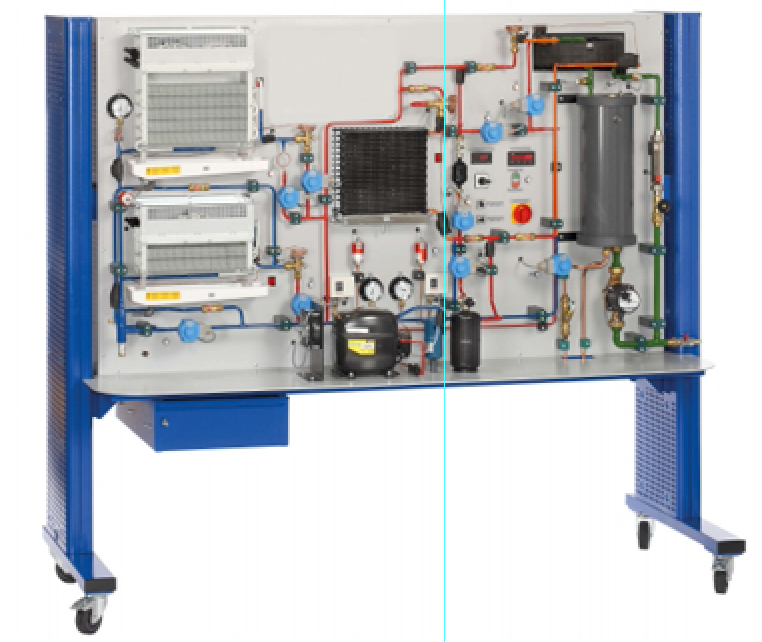
Refrigeration systems and heat pumps only differ in the
definition of their use, but can be of the same design. For example, goods can
be refrigerated in a supermarket and the store heated with the waste heat. The
store can also be cooled with the same system in the summer. With the cooling
and heating operation can be investigated. Different operating modes can be
selected via solenoid valves. The refrigeration circuit with compressor and
condenser (heat exchanger with fan) includes two evaporators with fans
(refrigeration stage and freezing stage) and thermostatic expansion valves. The
two evaporators can be connected in parallel or in series. For the connection
in series the capillary tube serves as expansion element for the refrigeration
stage evaporator. The refrigerant circuit is connected to a glycol-water
circuit via a coaxial coil heat exchanger. Via solenoid valves the coaxial coil
heat exchanger can be switched as an evaporator or condenser. Thus the
glycol-water mixture in the tank can be heated or cooled. In pure cooling
operation (without heating function) the heat exchanger with fan as air-cooled
condenser dissipates the heat. This heat exchanger can be also switched as an
evaporator.
Learning Objectives/Experiments
Design, operation and key components of a heat pump or
refrigeration system
Representation of the thermodynamic cycle in the log p-h
diagram
Comparing different operating modes
Measurement of compressor capacity and heating or cooling
capacity in the glycol-water circuit
Determination of
Efficiency
Coefficient of performance of heat pump and refrigeration
system
Specific compressor load
Compressor pressure ratio
Specific cooling capacity
Specific refrigeration capacity
Comparing key figures of heat pump and refrigeration system
Specification
Air-to-water heat pump for cooling or heating operation
Different operating modes selectable via solenoid valves
Refrigeration circuit with compressor, condenser (heat
exchanger with fan), 2 evaporators with fan (refrigeration and freezing stage)
Glycol-water circuit with tank, pump and coaxial coil heat
exchanger
Coaxial coil heat exchanger and heat exchanger with fan can
both be used as condenser or Evaporator in the refrigeration circuit
1 thermostatic expansion valve each for all heat exchangers
and evaporators
1 additional evaporation pressure controller and 1 capillary
tube for the refrigeration stage evaporator
Displays for temperature, pressure, flow rate and power
consumption of the compressor
Refrigerant mass flow rate calculated in the software from
recorded measured values
Technical Data
Compressor
refrigeration capacity: 1561W at 5/40°C
power consumption: 759W at 5/40°C
Heat exchanger with fan
transfer area: 1,25m2
volumetric air flow rate: 650m3/h
Evaporators with fan
refrigeration stage transfer area: 1,21m2, volumetric air
flow rate: 80m3/h
freezing stage transfer area: 3,62m2, volumetric air flow
rate: 125m3/h
Refrigerant: R513A, GWP: 631
filling volume: 1,5kg, CO2-equivalent: 0,9t
Measuring ranges
temperature: 11x -50…150°C
pressure: 2x -1…15bar, 1x -1…24bar
flow rate: 2,5…65g/s
power: 0…1150W
230V, 50Hz, 1 phase
230V, 60Hz, 1 phase; 120V, 60Hz, 1 phase
quick overview :
Refrigeration systems and heat pumps only differ in the
definition of their use, but can be of the same design. For example, goods can
be refrigerated in a supermarket and the store heated with the waste heat. The
store can also be cooled with the same system in the summer. With the cooling
and heating operation can be investigated. Different operating modes can be
selected via solenoid valves. The refrigeration circuit with compressor and
condenser (heat exchanger with fan) includes two evaporators with fans
(refrigeration stage and freezing stage) and thermostatic expansion valves. The
two evaporators can be connected in parallel or in series. For the connection
in series the capillary tube serves as expansion element for the refrigeration
stage evaporator. The refrigerant circuit is connected to a glycol-water
circuit via a coaxial coil heat exchanger. Via solenoid valves the coaxial coil
heat exchanger can be switched as an evaporator or condenser. Thus the
glycol-water mixture in the tank can be heated or cooled. In pure cooling
operation (without heating function) the heat exchanger with fan as air-cooled
condenser dissipates the heat. This heat exchanger can be also switched as an
evaporator.
Learning Objectives/Experiments
Design, operation and key components of a heat pump or
refrigeration system
Representation of the thermodynamic cycle in the log p-h
diagram
Comparing different operating modes
Measurement of compressor capacity and heating or cooling
capacity in the glycol-water circuit
Determination of
Efficiency
Coefficient of performance of heat pump and refrigeration
system
Specific compressor load
Compressor pressure ratio
Specific cooling capacity
Specific refrigeration capacity
Comparing key figures of heat pump and refrigeration system
Specification
Air-to-water heat pump for cooling or heating operation
Different operating modes selectable via solenoid valves
Refrigeration circuit with compressor, condenser (heat
exchanger with fan), 2 evaporators with fan (refrigeration and freezing stage)
Glycol-water circuit with tank, pump and coaxial coil heat
exchanger
Coaxial coil heat exchanger and heat exchanger with fan can
both be used as condenser or Evaporator in the refrigeration circuit
1 thermostatic expansion valve each for all heat exchangers
and evaporators
1 additional evaporation pressure controller and 1 capillary
tube for the refrigeration stage evaporator
Displays for temperature, pressure, flow rate and power
consumption of the compressor
Refrigerant mass flow rate calculated in the software from
recorded measured values
Technical Data
Compressor
refrigeration capacity: 1561W at 5/40°C
power consumption: 759W at 5/40°C
Heat exchanger with fan
transfer area: 1,25m2
volumetric air flow rate: 650m3/h
Evaporators with fan
refrigeration stage transfer area: 1,21m2, volumetric air
flow rate: 80m3/h
freezing stage transfer area: 3,62m2, volumetric air flow
rate: 125m3/h
Refrigerant: R513A, GWP: 631
filling volume: 1,5kg, CO2-equivalent: 0,9t
Measuring ranges
temperature: 11x -50…150°C
pressure: 2x -1…15bar, 1x -1…24bar
flow rate: 2,5…65g/s
power: 0…1150W
230V, 50Hz, 1 phase
230V, 60Hz, 1 phase; 120V, 60Hz, 1 phase
Product
Reviews
add Review
reviews
No Review Yet.
Related
Products
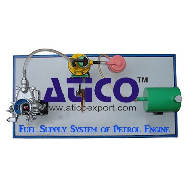
Fuel Supply System Of Petrol Engine
Fuel Supply System Of Petrol EngineFuel is supplied under pr...
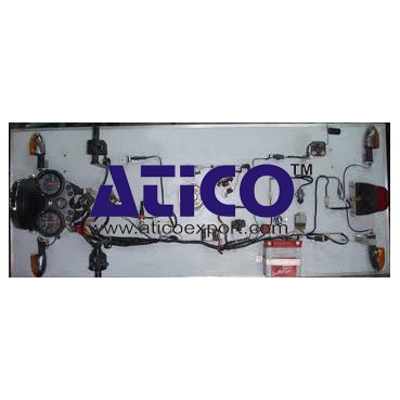
It is an open type instructional apparatus with second hand...
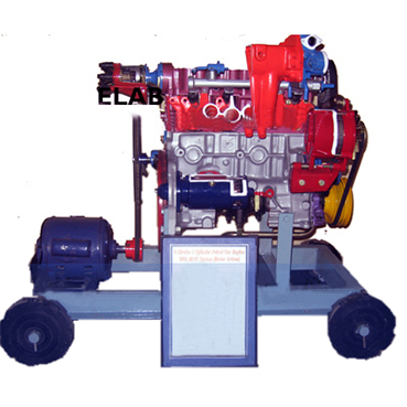
Distributor is connected to camshaft and cam shaft is connec...
The device is consisting of the front able with wheel &b...
Specification: 1. Experimental setup to demonstrate simple...
Technical Description: Supplementary set extends the scope...
Equilibrium Single Plane, Statically Det...
Equilibrium in a Single Plane, Statically Determinate S...
Equilibrium Of Moments On Pulleys
Equilibrium Of Moments On Pulleys Manufacturer and Supplier...
Copyrights © 2025 All Rights Reserved by Atico
Product
Reviews
add Review
reviews
No Review Yet.