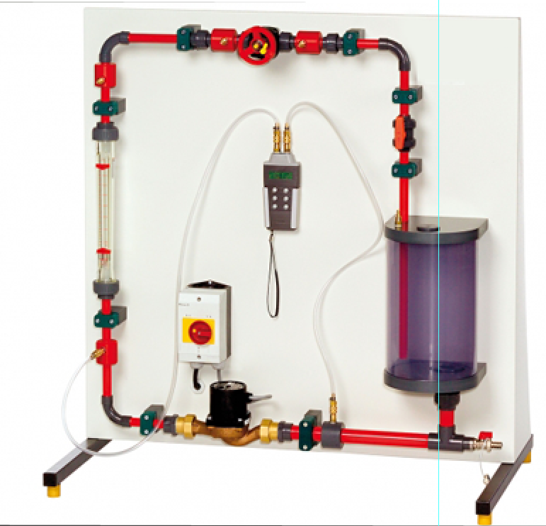
Hydraulic Circuit With Centrifugal Pump
Categories: Engineering Lab EquipmentHydraulic circuits are designed according to their task and their area of application. Designing hydraulic circuits requires knowledge of flow behaviour and pressure losses in valves and fittings, as...


Product
Description
quick overview :
Product
Reviews
add Review
reviews
No Review Yet.
Related
Products
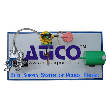
Fuel Supply System Of Petrol Engine
Fuel Supply System Of Petrol EngineFuel is supplied under pr...
It is an open type instructional apparatus with second hand...
Distributor is connected to camshaft and cam shaft is connec...
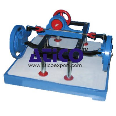
The device is consisting of the front able with wheel &b...
Specification: 1. Experimental setup to demonstrate simple...
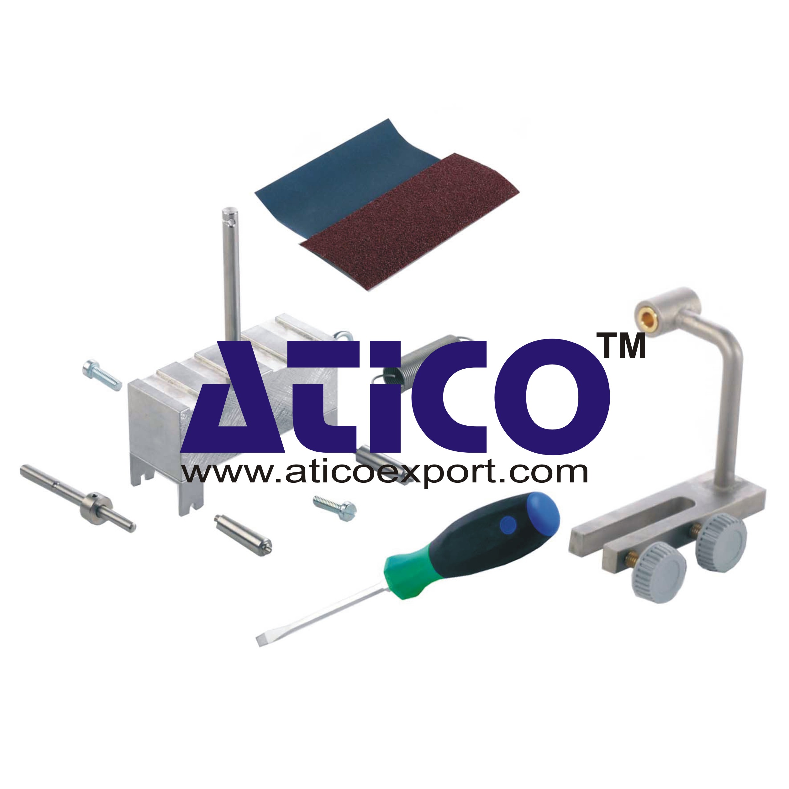
Technical Description: Supplementary set extends the scope...
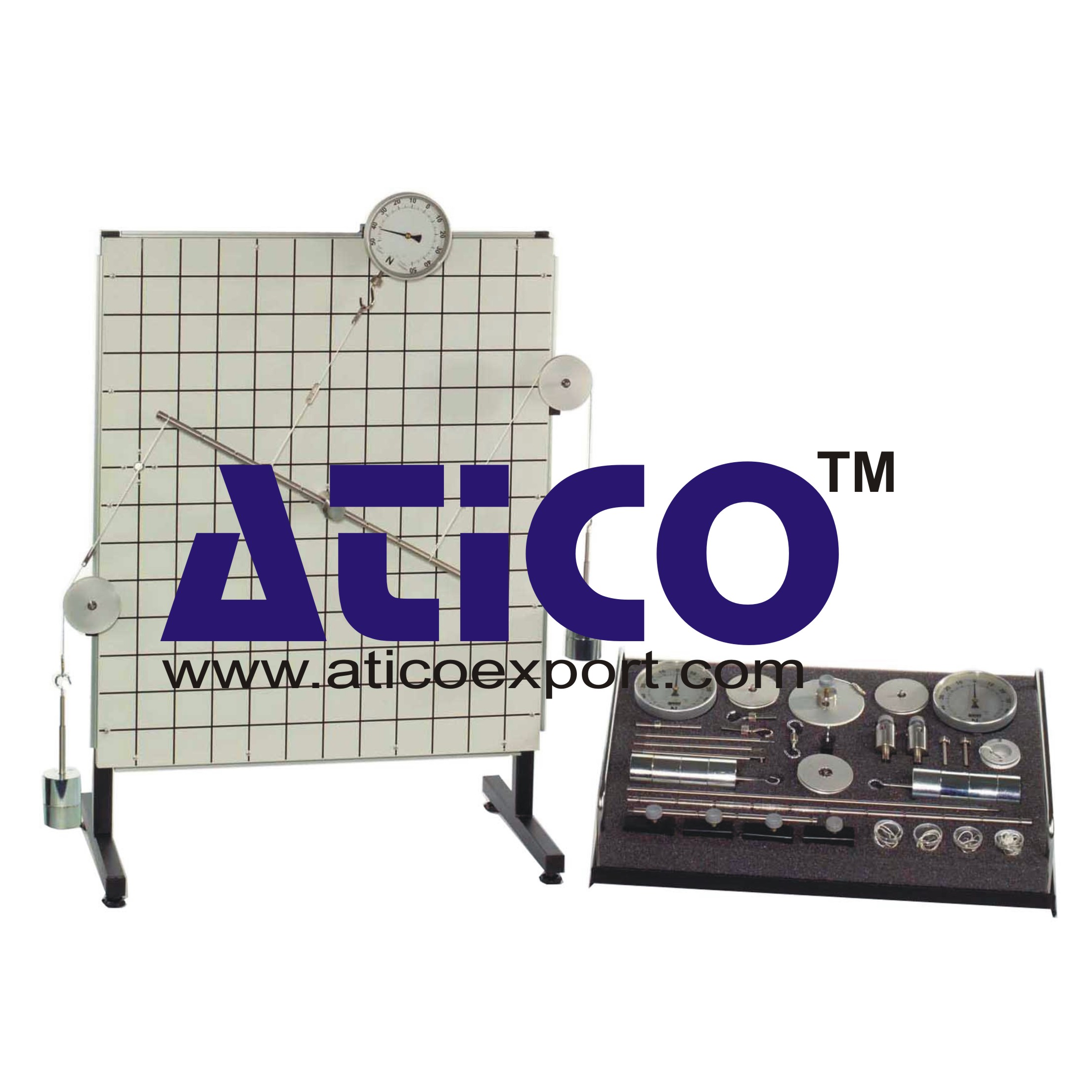
Equilibrium Single Plane, Statically Det...
Equilibrium in a Single Plane, Statically Determinate S...
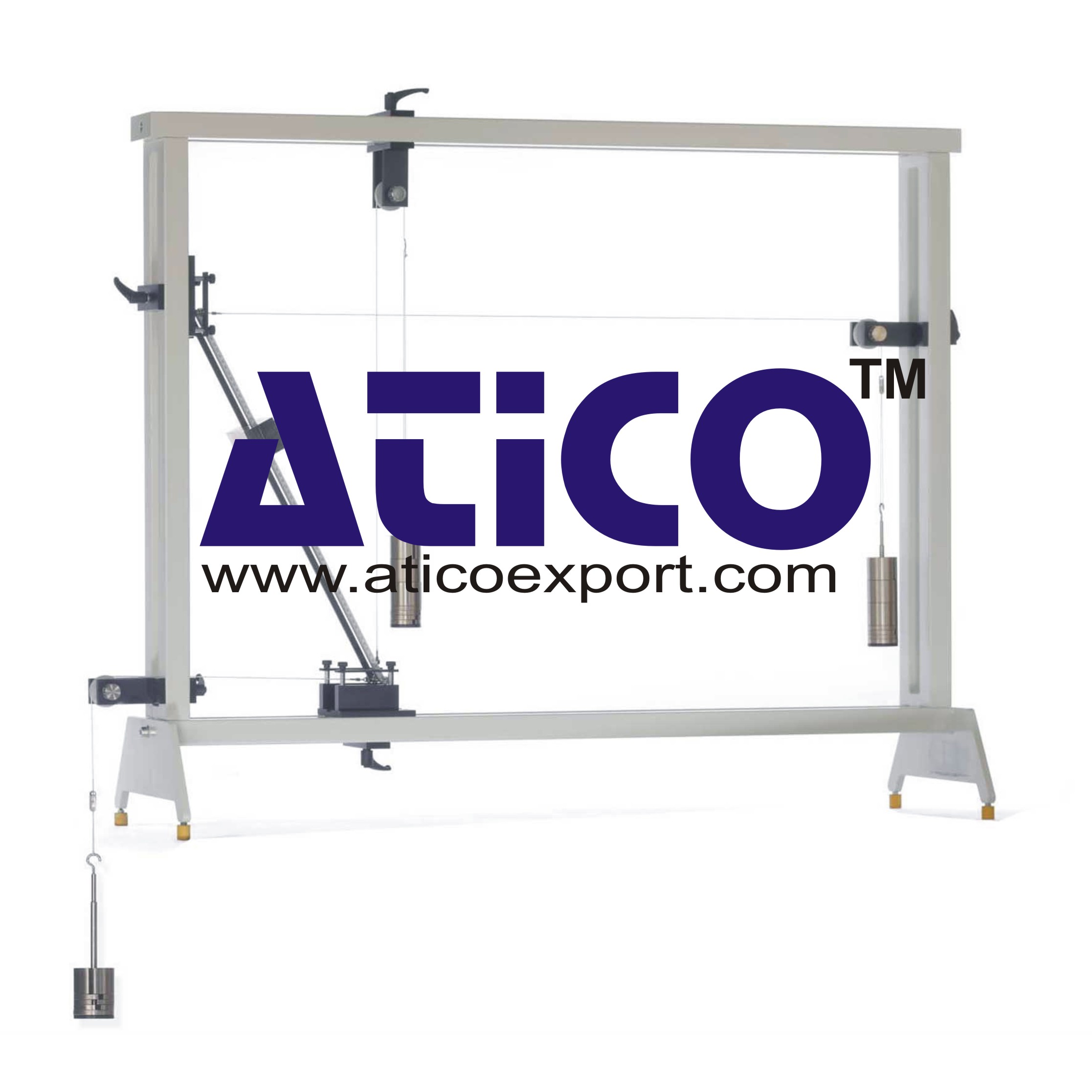
Equilibrium Of Moments On Pulleys
Equilibrium Of Moments On Pulleys Manufacturer and Supplier...
Product
Reviews
add Review
reviews
No Review Yet.