Installation Technology Losses In A Pipe System
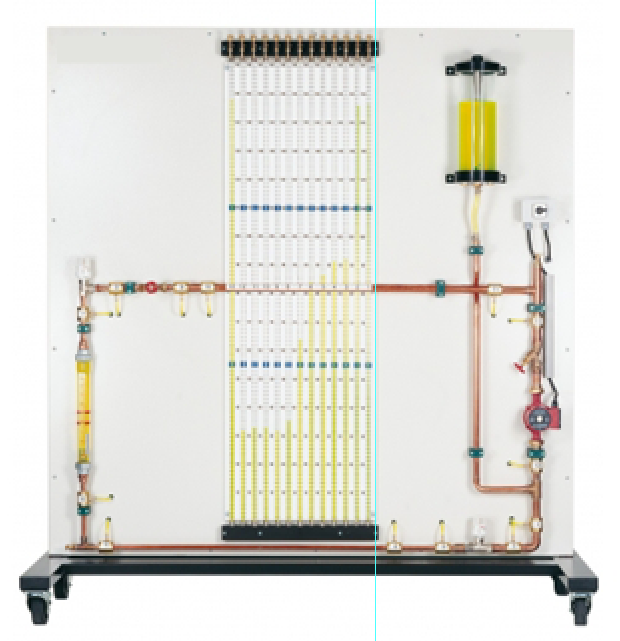
Categories: Engineering Lab EquipmentWhen water flows through a pipe system there are resistances as a result of changes in direction, valves and fittings and pipe friction. The flow resistances are directly dependent on the geometry of...
Product
Description
When water flows through a pipe system there are resistances
as a result of changes in direction, valves and fittings and pipe friction. The
flow resistances are directly dependent on the geometry of the pipe elements
and the number and type of fittings. In addition, the flow velocity plays a key
role in the occurrence of pressure losses. The unit can be used to investigate
and visualise the pressure distribution in a pipe system. The trainer enables
the examination by experiment of different influencing factors on the pressure
losses in real pipe systems. The relationship between pump characteristic and
system characteristic is studied in the experiment. The pipe elements used are
commercially standard components in heating and sanitary engineering. The clear
panel is mounted on a sturdy, movable frame.
Learning Objectives/Experiments
Pressure curve in a closed pipe system with circulation pump
Influence of pipe diameter, flow velocity, change in
cross-section and pipe fittings on the pressure losses
Determination of pump characteristics, system
characteristics and the operating point
Specification
Investigation of the pressure losses at contractions, pipe
angles, pipe bends, valves and fittings and pipe elements of different diameter
Pipe elements are commercially standard components in
heating and sanitary engineering
Clear panel mounted on a sturdy, movable frame
Closed water circuit with pump and tank
Integrated bleed valve on manometer and in the pipe section
Flow measurement using rotameter
Measurement of the pressure distribution at 13 pressure
measuring points, display with 13 tube manometers
Technical Data
Pump
3 stages
max. flow rate: 4,5m³/h
max. head: 6m
Tank: approx. 5L
Measuring ranges
flow rate: 100…1000L/h
pressure: 1600mmWC
230V, 50Hz, 1 phase
quick overview :
When water flows through a pipe system there are resistances
as a result of changes in direction, valves and fittings and pipe friction. The
flow resistances are directly dependent on the geometry of the pipe elements
and the number and type of fittings. In addition, the flow velocity plays a key
role in the occurrence of pressure losses. The unit can be used to investigate
and visualise the pressure distribution in a pipe system. The trainer enables
the examination by experiment of different influencing factors on the pressure
losses in real pipe systems. The relationship between pump characteristic and
system characteristic is studied in the experiment. The pipe elements used are
commercially standard components in heating and sanitary engineering. The clear
panel is mounted on a sturdy, movable frame.
Learning Objectives/Experiments
Pressure curve in a closed pipe system with circulation pump
Influence of pipe diameter, flow velocity, change in
cross-section and pipe fittings on the pressure losses
Determination of pump characteristics, system
characteristics and the operating point
Specification
Investigation of the pressure losses at contractions, pipe
angles, pipe bends, valves and fittings and pipe elements of different diameter
Pipe elements are commercially standard components in
heating and sanitary engineering
Clear panel mounted on a sturdy, movable frame
Closed water circuit with pump and tank
Integrated bleed valve on manometer and in the pipe section
Flow measurement using rotameter
Measurement of the pressure distribution at 13 pressure
measuring points, display with 13 tube manometers
Technical Data
Pump
3 stages
max. flow rate: 4,5m³/h
max. head: 6m
Tank: approx. 5L
Measuring ranges
flow rate: 100…1000L/h
pressure: 1600mmWC
230V, 50Hz, 1 phase
Product
Reviews
add Review
reviews
No Review Yet.
Copyrights © 2025 All Rights Reserved by Atico



Product
Reviews
add Review
reviews
No Review Yet.