Power Factor Load Bank

Categories: Engineering Lab Equipment

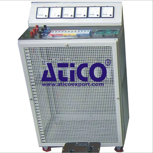
DescriptionThe Power Factor Load Bank is a free-standing and mobile unit. It gives predictable load and power factor characteristics, useful for many different power systems experiments. It also helps...


title icon
Product

Description

Description

The Power Factor Load Bank is a free-standing and mobile unit. It gives predictable load and power factor characteristics, useful for many different power systems experiments. It also helps to show the principles of a static VAr compensator used in industrial plants and large factories. The load bank provides three separate inputs: Lines 1, 2 and 3. This allows it to work with single and three-phase circuits. Each line is independent, which allows it to connect with the others as a star or delta load. The load bank includes three separate banks of resistive, inductive and capacitive loads. They give a choice and combination of types of loads to give unity (resistive only) and leading or lagging power factor. A voltage-selector switch allows the load bank to work with different line voltages for single and three-phase circuits. Each bank (line) may be set to different values, to give an unbalanced load for balanced and unbalanced load tests. The top of the load bank includes a useful worktop for any additional instruments or for recording results. The load bank has small wheels, for easy mobility. This saves time setting up experiments and clearing the classroom or laboratory after use. Note: This load bank is only suitable as a load for a.c. circuits.

Learning Outcomes

Note: This is a load bank for use with other equipment. Its User Guide does not include full experiment procedures.
When used with other suitable equipment it can show:
• Balanced loading
• Unbalanced loading
• Varying load with fi xed lagging or leading power factor
• Neutral displacement
• Relationship between Watts, VArs and VA
• Power factor correction
• Methods of determining power factor
• Static VAr compensators

Specifications

Nett dimensions:

1500 mm high x 1030 mm front to back x 960 mm wide

Nett weight:

370 kg

Packed volume:

1.87 m3

Packed weight:

Approximately 450 kg

Loads:

Three separate variable loads at 1 kVA (3 kVA total for three

phase)

Power factors:

• Unity, 0.8, 0.6, 0.4 and low* lagging

• Unity, 0.8, 0.6, 0.4 and low* leading

 *Low is approximately 0.2 pf but varies slightly due to component tolerances.


Operating Conditions

Operating Enviroment:

Laboratory Enviroment

Storage Temprature Range :

–25°C to +55°C (when packed for transport)

Operating Temprature range:

+5°C to +40°C

Operating relative humidity range:

80% at temperatures < 31°C decreasing linearly to 50% at 40°C


title icon
Product

Reviews

add Review
reviews

    No Review Yet.

quick overview :

Description

The Power Factor Load Bank is a free-standing and mobile unit. It gives predictable load and power factor characteristics, useful for many different power systems experiments. It also helps to show the principles of a static VAr compensator used in industrial plants and large factories. The load bank provides three separate inputs: Lines 1, 2 and 3. This allows it to work with single and three-phase circuits. Each line is independent, which allows it to connect with the others as a star or delta load. The load bank includes three separate banks of resistive, inductive and capacitive loads. They give a choice and combination of types of loads to give unity (resistive only) and leading or lagging power factor. A voltage-selector switch allows the load bank to work with different line voltages for single and three-phase circuits. Each bank (line) may be set to different values, to give an unbalanced load for balanced and unbalanced load tests. The top of the load bank includes a useful worktop for any additional instruments or for recording results. The load bank has small wheels, for easy mobility. This saves time setting up experiments and clearing the classroom or laboratory after use. Note: This load bank is only suitable as a load for a.c. circuits.

Learning Outcomes

Note: This is a load bank for use with other equipment. Its User Guide does not include full experiment procedures.
When used with other suitable equipment it can show:
• Balanced loading
• Unbalanced loading
• Varying load with fi xed lagging or leading power factor
• Neutral displacement
• Relationship between Watts, VArs and VA
• Power factor correction
• Methods of determining power factor
• Static VAr compensators

Specifications

Nett dimensions:

1500 mm high x 1030 mm front to back x 960 mm wide

Nett weight:

370 kg

Packed volume:

1.87 m3

Packed weight:

Approximately 450 kg

Loads:

Three separate variable loads at 1 kVA (3 kVA total for three

phase)

Power factors:

• Unity, 0.8, 0.6, 0.4 and low* lagging

• Unity, 0.8, 0.6, 0.4 and low* leading

 *Low is approximately 0.2 pf but varies slightly due to component tolerances.


Operating Conditions

Operating Enviroment:

Laboratory Enviroment

Storage Temprature Range :

–25°C to +55°C (when packed for transport)

Operating Temprature range:

+5°C to +40°C

Operating relative humidity range:

80% at temperatures < 31°C decreasing linearly to 50% at 40°C

title icon
Product

Reviews

add Review
reviews

    No Review Yet.