Refrigeration Circuit With Variable Load
Categories: Engineering Lab EquipmentIt examines a refrigeration circuit under an adjustable load. The refrigeration circuit consists of a compressor, a condenser with fan, a thermostatic expansion valve and a coaxial coil heat exchanger...


Product
Description
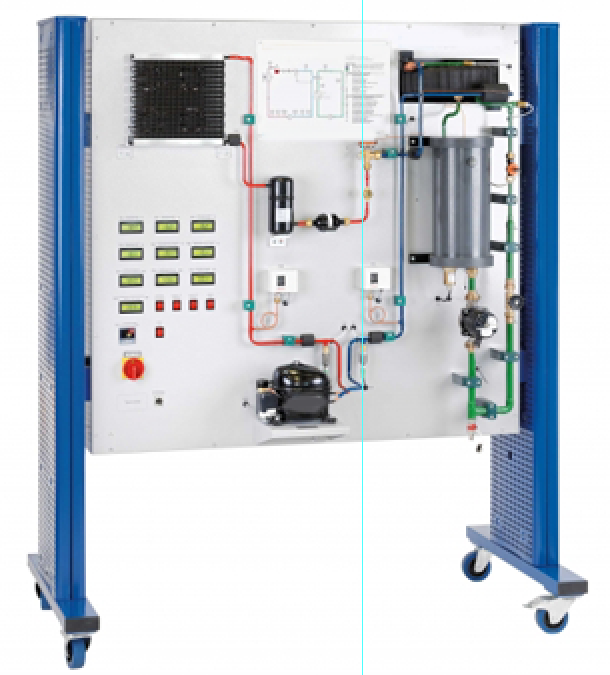
It examines a refrigeration circuit under an adjustable
load. The refrigeration circuit consists of a compressor, a condenser with fan,
a thermostatic expansion valve and a coaxial coil heat exchanger as evaporator.
A water circuit serves as load, consisting of a tank with a heater and a pump.
The temperature in the tank is adjusted at a controller. The purpose of this
refrigeration circuit is the production of cold water. The water flows through
the jacket of the coaxial coil heat exchanger, transfers heat to the
refrigerant and thereby cools down. All relevant measured values are recorded
by sensors. The simultaneous transmission of the measured values to a data
recording software enables easy analysis and the representation of the process
in the log p-h diagram. The software also displays the key characteristic
variables of the process, such as the compressor pressure ratio and the
coefficient of performance. The clearly arranged components aid understanding.
Learning Objectives/Experiments
Design and components of a refrigeration system
Compressor
Condenser
Thermostatic expansion valve
Evaporator
Pressure switch
Representation of the thermodynamic cycle in the log p-h
diagram
Determination of important characteristic variables
Coefficient of performance
Refrigeration capacity
Compressor work
Operating behaviour under load
Specification
Investigation of a refrigeration circuit with water circuit
as load
Refrigeration circuit with compressor, condenser with fan,
thermostatic expansion valve and coaxial coil heat exchanger as evaporator
Water circuit with pump, tank with heater as cooling load at
the evaporator
Heater with controller to adjust the tank temperature
Recording of the refrigerant mass flow rate as a function of
the pressure difference
Recording of all relevant measured values
Technical Data
Compressor
refrigeration capacity: approx. 479W at 7,2/54,4°C
power consumption: 168W at 7,2/54,4°C
Evaporator
refrigerant volume: 0,4L
water volume: 0,8L
Condenser
transfer area: approx. 1,25m2
fan power consumption: 4x 12W
Pump
max. flow rate: 1,9m3/h
max. head: 1,4m
Tank
volume: approx. 4,5L
heater: approx. 450W
Refrigerant: R513A, GWP: 631
filling volume: 800g
CO2-equivalent: 0,5t
Measuring ranges
pressure: 2x -1…15bar
power: 0…750W
temperature: 6x 0…100°C
flow rate: 0,05…1,8L/min (water)
flow rate: 0…50kg/h (refrigerant)
230V, 50Hz, 1 phase
230V, 60Hz, 1 phase
120V, 60Hz, 1 phase
quick overview :
It examines a refrigeration circuit under an adjustable
load. The refrigeration circuit consists of a compressor, a condenser with fan,
a thermostatic expansion valve and a coaxial coil heat exchanger as evaporator.
A water circuit serves as load, consisting of a tank with a heater and a pump.
The temperature in the tank is adjusted at a controller. The purpose of this
refrigeration circuit is the production of cold water. The water flows through
the jacket of the coaxial coil heat exchanger, transfers heat to the
refrigerant and thereby cools down. All relevant measured values are recorded
by sensors. The simultaneous transmission of the measured values to a data
recording software enables easy analysis and the representation of the process
in the log p-h diagram. The software also displays the key characteristic
variables of the process, such as the compressor pressure ratio and the
coefficient of performance. The clearly arranged components aid understanding.
Learning Objectives/Experiments
Design and components of a refrigeration system
Compressor
Condenser
Thermostatic expansion valve
Evaporator
Pressure switch
Representation of the thermodynamic cycle in the log p-h
diagram
Determination of important characteristic variables
Coefficient of performance
Refrigeration capacity
Compressor work
Operating behaviour under load
Specification
Investigation of a refrigeration circuit with water circuit
as load
Refrigeration circuit with compressor, condenser with fan,
thermostatic expansion valve and coaxial coil heat exchanger as evaporator
Water circuit with pump, tank with heater as cooling load at
the evaporator
Heater with controller to adjust the tank temperature
Recording of the refrigerant mass flow rate as a function of
the pressure difference
Recording of all relevant measured values
Technical Data
Compressor
refrigeration capacity: approx. 479W at 7,2/54,4°C
power consumption: 168W at 7,2/54,4°C
Evaporator
refrigerant volume: 0,4L
water volume: 0,8L
Condenser
transfer area: approx. 1,25m2
fan power consumption: 4x 12W
Pump
max. flow rate: 1,9m3/h
max. head: 1,4m
Tank
volume: approx. 4,5L
heater: approx. 450W
Refrigerant: R513A, GWP: 631
filling volume: 800g
CO2-equivalent: 0,5t
Measuring ranges
pressure: 2x -1…15bar
power: 0…750W
temperature: 6x 0…100°C
flow rate: 0,05…1,8L/min (water)
flow rate: 0…50kg/h (refrigerant)
230V, 50Hz, 1 phase
230V, 60Hz, 1 phase
120V, 60Hz, 1 phase
Product
Reviews
add Review
reviews
No Review Yet.
Related
Products
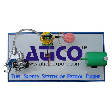
Fuel Supply System Of Petrol Engine
Fuel Supply System Of Petrol EngineFuel is supplied under pr...
It is an open type instructional apparatus with second hand...
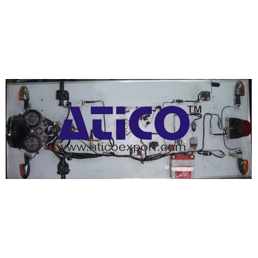
Distributor is connected to camshaft and cam shaft is connec...
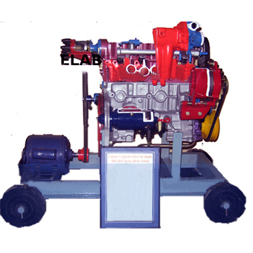
The device is consisting of the front able with wheel &b...
Specification: 1. Experimental setup to demonstrate simple...
Technical Description: Supplementary set extends the scope...
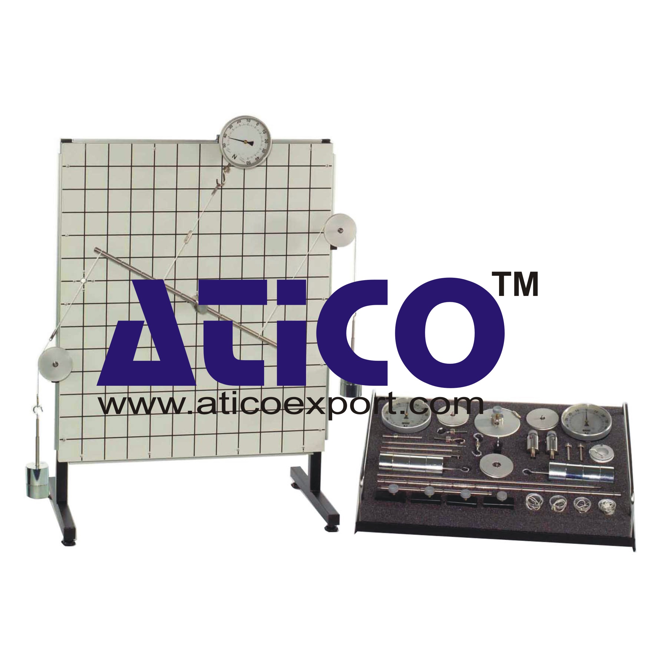
Equilibrium Single Plane, Statically Det...
Equilibrium in a Single Plane, Statically Determinate S...
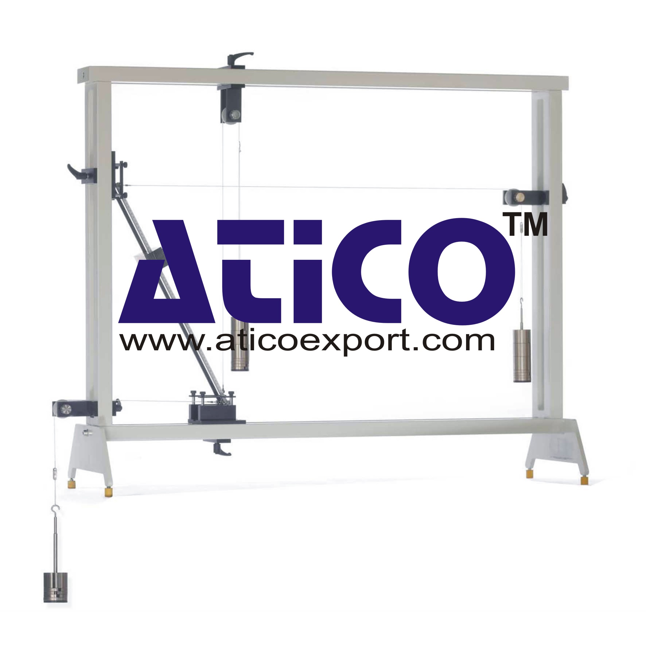
Equilibrium Of Moments On Pulleys
Equilibrium Of Moments On Pulleys Manufacturer and Supplier...
Product
Reviews
add Review
reviews
No Review Yet.