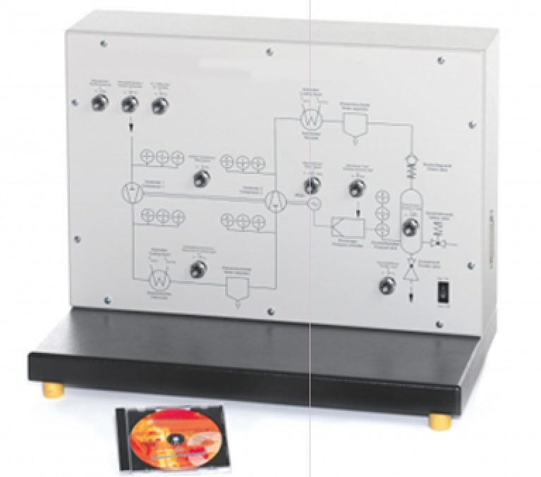
Simulation of a Two Stage Air Compressor
Categories: Engineering Lab EquipmentWhen operating real compressor plants in industry, the specified process parameters must be adhered to. Certain operating conditions must be avoided in order to prevent damage to the plant.The experim...


Product
Description
quick overview :
Product
Reviews
add Review
reviews
No Review Yet.
Related
Products
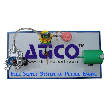
Fuel Supply System Of Petrol Engine
Fuel Supply System Of Petrol EngineFuel is supplied under pr...
It is an open type instructional apparatus with second hand...
Distributor is connected to camshaft and cam shaft is connec...
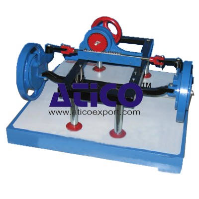
The device is consisting of the front able with wheel &b...
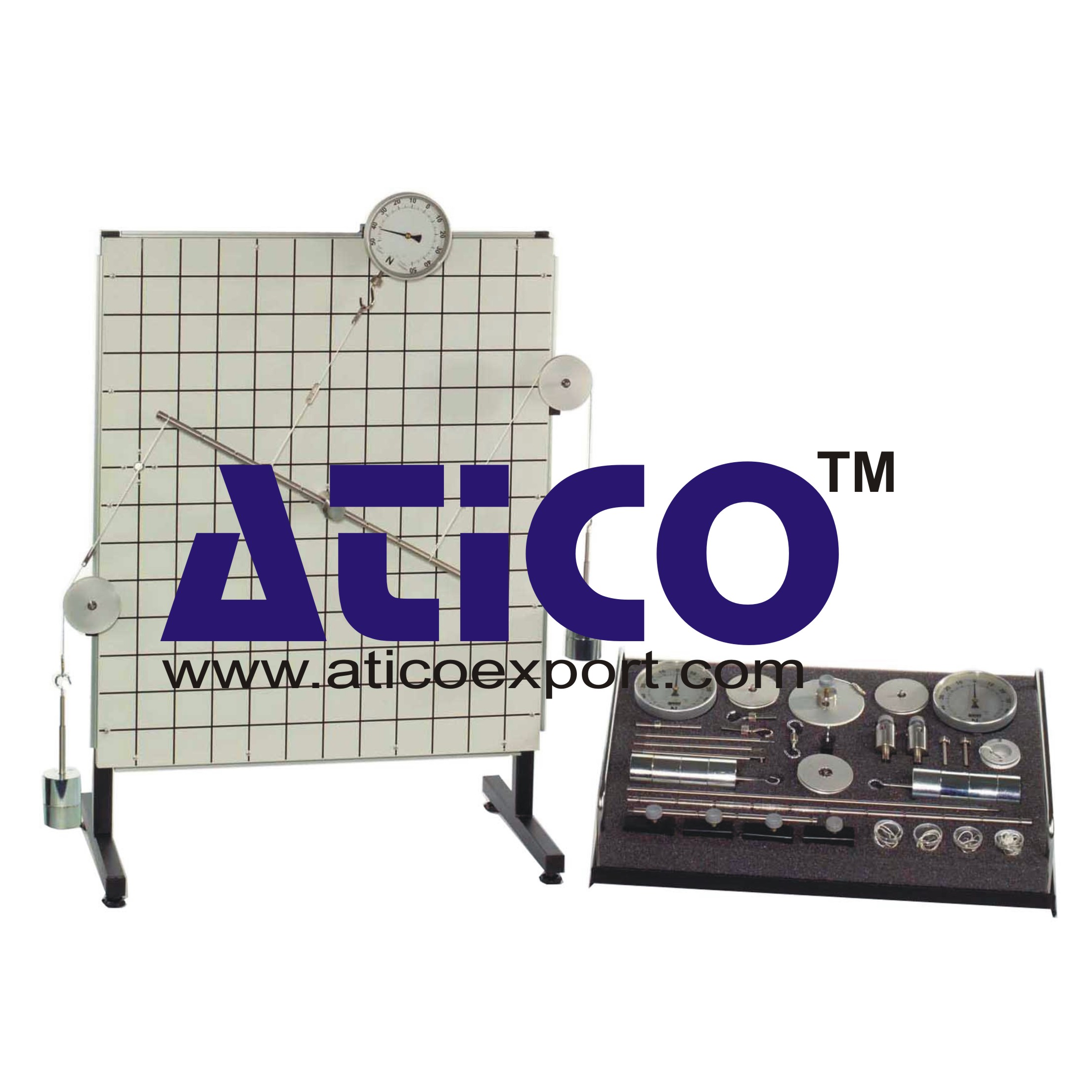
Specification: 1. Experimental setup to demonstrate simple...
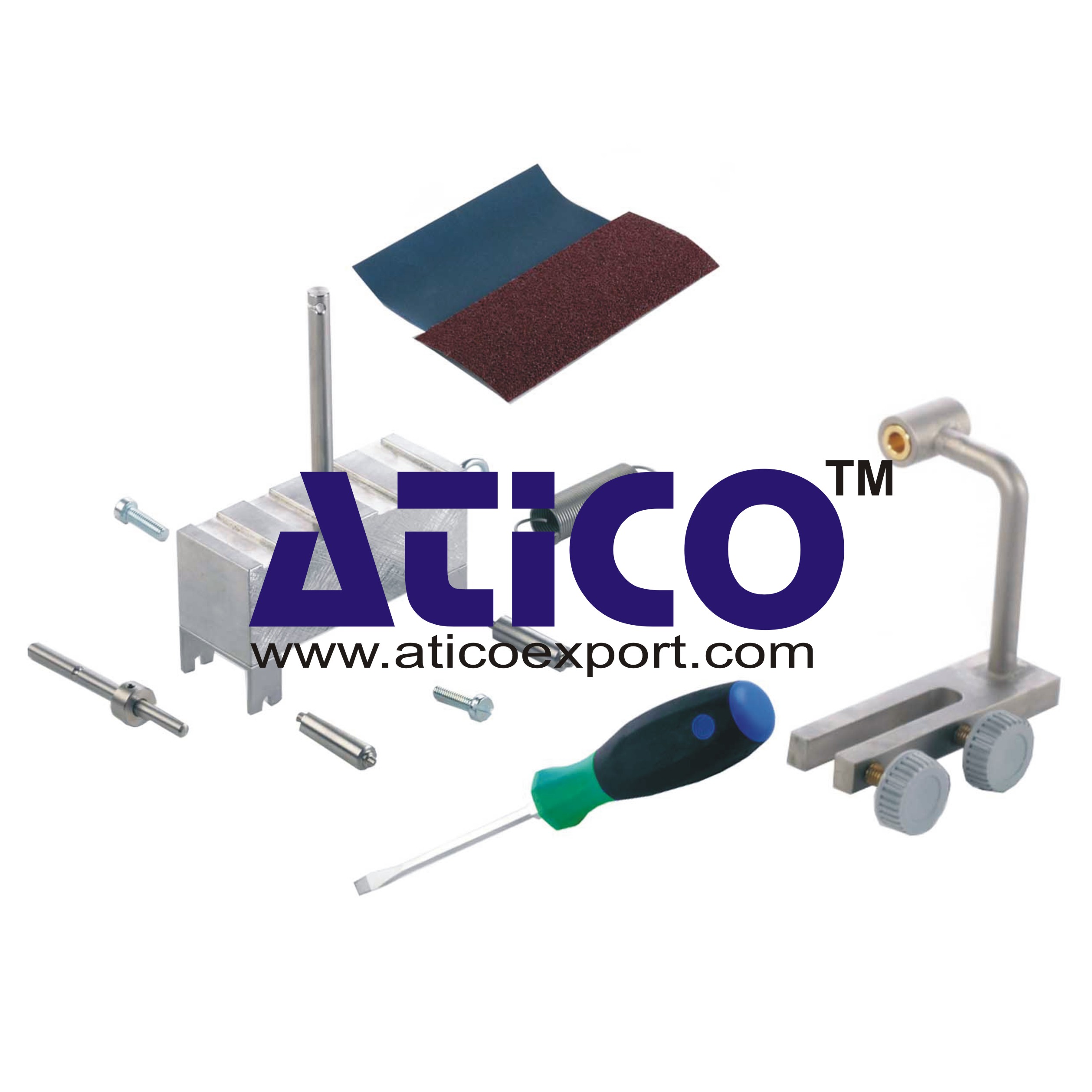
Technical Description: Supplementary set extends the scope...
Equilibrium Single Plane, Statically Det...
Equilibrium in a Single Plane, Statically Determinate S...
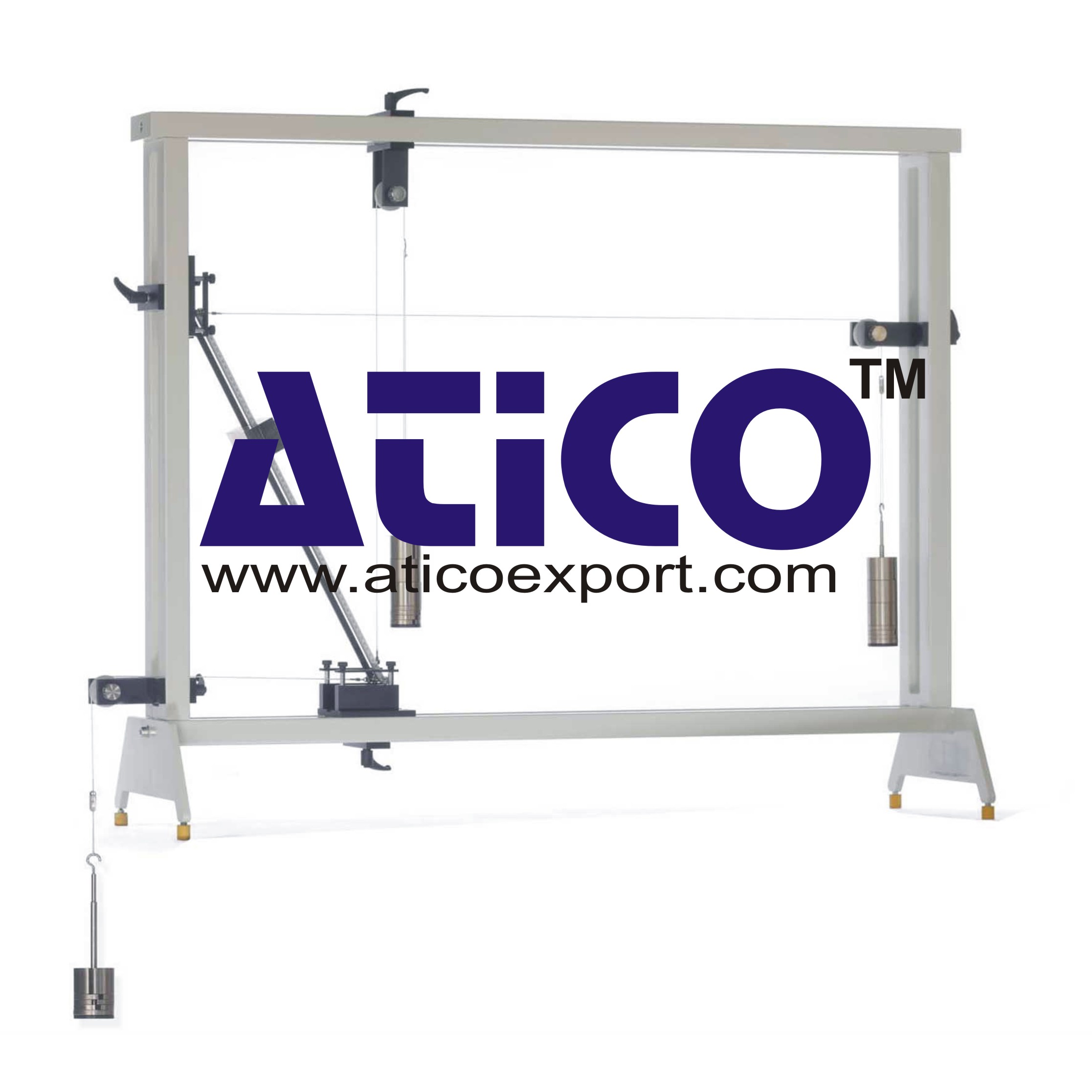
Equilibrium Of Moments On Pulleys
Equilibrium Of Moments On Pulleys Manufacturer and Supplier...
Product
Reviews
add Review
reviews
No Review Yet.