Thermodynamics Of The Refrigeration Circuit
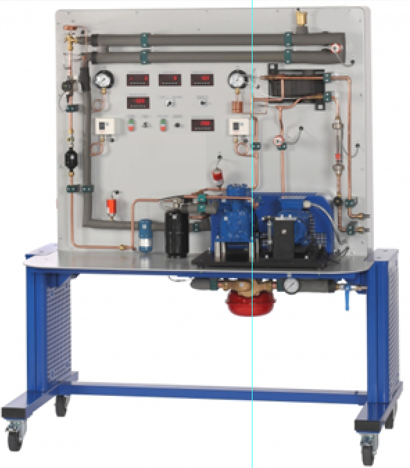
Categories: Engineering Lab EquipmentIn this trainer, great care was taken to make the thermodynamic processes in the refrigeration system as transparent as possible. The capacities of compressor, evaporator and condenser can be measured...


Product
Description
In this trainer, great care was taken to make the
thermodynamic processes in the refrigeration system as transparent as possible.
The capacities of compressor, evaporator and condenser can be measured.
Pressure and temperature measuring points are located at all the relevant
locations to also allow for the pressure and heat losses in a refrigeration
system to be investigated in detail. The refrigeration circuit of contains an
open compressor with variable speed, a water-cooled condenser, a thermostatic expansion
valve and an evaporator heated by a hot water circuit. The compressor is driven
via a pendulum bearing motor with frequency converter for speed adjustment. A
force transducer permits the measuring of the drive torque. Using the speed the
mechanical drive power of the compressor can thus be determined. The electrical
heating power of the hot water circuit can be freely adjusted and is displayed.
The condenser capacity is measured via the cooling water flow.
Learning Objectives/Experiments
Cyclic process in the log p-h diagram
Comparison of the real cyclic process and the ideal cyclic
process
Balances at the evaporator and condenser
Calculation of the motor power via speed and torque
Determination of losses
Calculation of the coefficient of performance
Operating behaviour under load
Non-steady-state operating behaviour
Specification
Thermodynamic investigation of a refrigeration circuit
Refrigeration circuit with open compressor, water-cooled
condenser, thermostatic expansion Valve and indirectly heated evaporator
Compressor drive with speed-controlled motor via V-belt
Motor on pendulum bearing for torque measurement
Tube evaporator with hot water circuit as cooling load
Water-cooled coaxial coil heat exchanger as condenser
Displays for temperature, pressure, flow rate, speed, torque
and power at the equipment
Technical Data
Open compressor
refrigeration capacity: approx. 965W (at a speed of
1450min-1 and 5/40°C)
Heater: 1x 1000W
Condenser, capacity: 1300W
Refrigerant
R513A, GWP: 631, filling volume: 2kg, CO2-equivalent: 1,3t
Measuring ranges
temperature: 9x -30…100°C, 1x 0…100°C
pressure: 1x -1…9bar, 1x -1…24bar, 4x -1…15bar
torque: (compressor) 0…10Nm
speed: (compressor) 0…2500min-1
power consumption: (compressor) 0…1125W
power: (heater) 0…1125W
flow rate: (water) 5…70g/s
flow rate: (refrigerant) 0…0,5L/min
230V, 50Hz, 1 phase
230V, 60Hz, 1 phase; 230V, 60Hz, 3 phases
quick overview :
In this trainer, great care was taken to make the
thermodynamic processes in the refrigeration system as transparent as possible.
The capacities of compressor, evaporator and condenser can be measured.
Pressure and temperature measuring points are located at all the relevant
locations to also allow for the pressure and heat losses in a refrigeration
system to be investigated in detail. The refrigeration circuit of contains an
open compressor with variable speed, a water-cooled condenser, a thermostatic expansion
valve and an evaporator heated by a hot water circuit. The compressor is driven
via a pendulum bearing motor with frequency converter for speed adjustment. A
force transducer permits the measuring of the drive torque. Using the speed the
mechanical drive power of the compressor can thus be determined. The electrical
heating power of the hot water circuit can be freely adjusted and is displayed.
The condenser capacity is measured via the cooling water flow.
Learning Objectives/Experiments
Cyclic process in the log p-h diagram
Comparison of the real cyclic process and the ideal cyclic
process
Balances at the evaporator and condenser
Calculation of the motor power via speed and torque
Determination of losses
Calculation of the coefficient of performance
Operating behaviour under load
Non-steady-state operating behaviour
Specification
Thermodynamic investigation of a refrigeration circuit
Refrigeration circuit with open compressor, water-cooled
condenser, thermostatic expansion Valve and indirectly heated evaporator
Compressor drive with speed-controlled motor via V-belt
Motor on pendulum bearing for torque measurement
Tube evaporator with hot water circuit as cooling load
Water-cooled coaxial coil heat exchanger as condenser
Displays for temperature, pressure, flow rate, speed, torque
and power at the equipment
Technical Data
Open compressor
refrigeration capacity: approx. 965W (at a speed of
1450min-1 and 5/40°C)
Heater: 1x 1000W
Condenser, capacity: 1300W
Refrigerant
R513A, GWP: 631, filling volume: 2kg, CO2-equivalent: 1,3t
Measuring ranges
temperature: 9x -30…100°C, 1x 0…100°C
pressure: 1x -1…9bar, 1x -1…24bar, 4x -1…15bar
torque: (compressor) 0…10Nm
speed: (compressor) 0…2500min-1
power consumption: (compressor) 0…1125W
power: (heater) 0…1125W
flow rate: (water) 5…70g/s
flow rate: (refrigerant) 0…0,5L/min
230V, 50Hz, 1 phase
230V, 60Hz, 1 phase; 230V, 60Hz, 3 phases
Product
Reviews
add Review
reviews
No Review Yet.
Related
Products
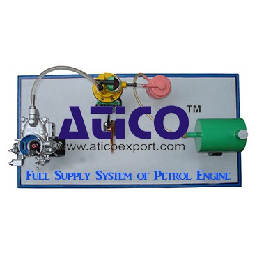
Fuel Supply System Of Petrol Engine
Fuel Supply System Of Petrol EngineFuel is supplied under pr...
It is an open type instructional apparatus with second hand...
Distributor is connected to camshaft and cam shaft is connec...
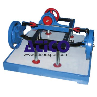
The device is consisting of the front able with wheel &b...
Specification: 1. Experimental setup to demonstrate simple...
Technical Description: Supplementary set extends the scope...
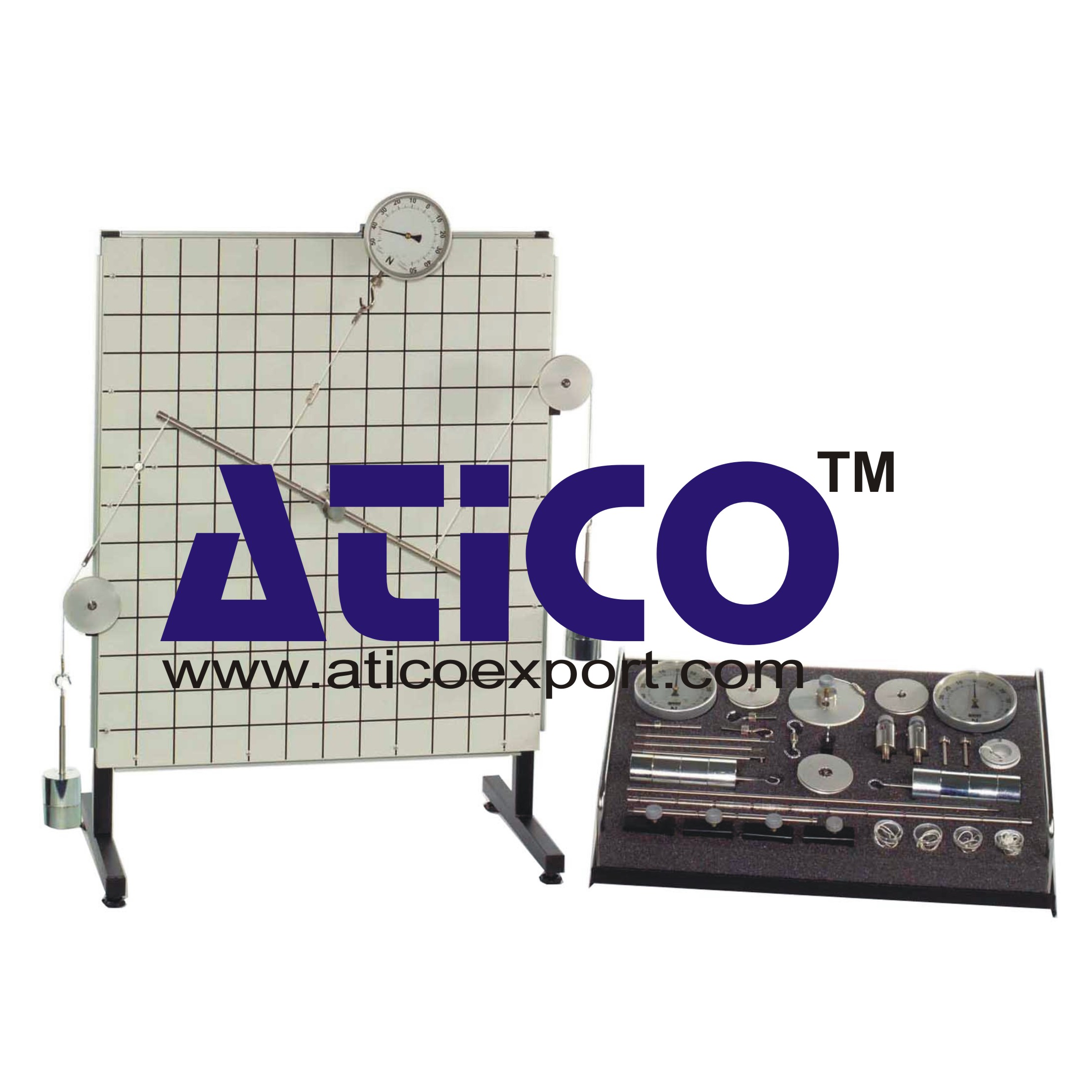
Equilibrium Single Plane, Statically Det...
Equilibrium in a Single Plane, Statically Determinate S...
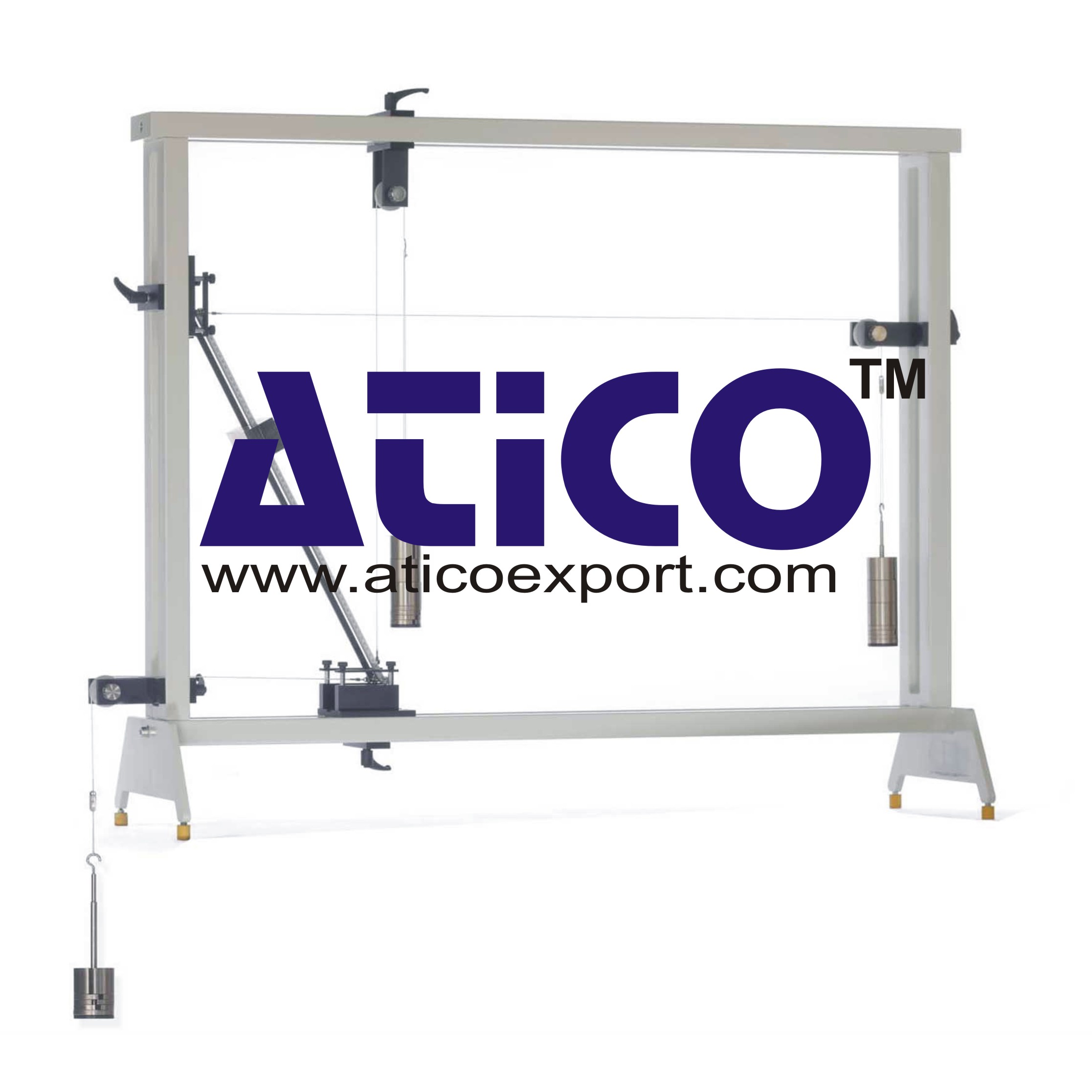
Equilibrium Of Moments On Pulleys
Equilibrium Of Moments On Pulleys Manufacturer and Supplier...
Product
Reviews
add Review
reviews
No Review Yet.