Advanced Cockpit Instrumentation Trainer
Categories: Aviation Maintenance Training EquipmentFeatures: The system combines Cockpit analog flight instrumentation, primary flight instrumentation, systems instrumentation and engine instrumentation. Trainer use the latest in GPS and Dig...


Product
Description
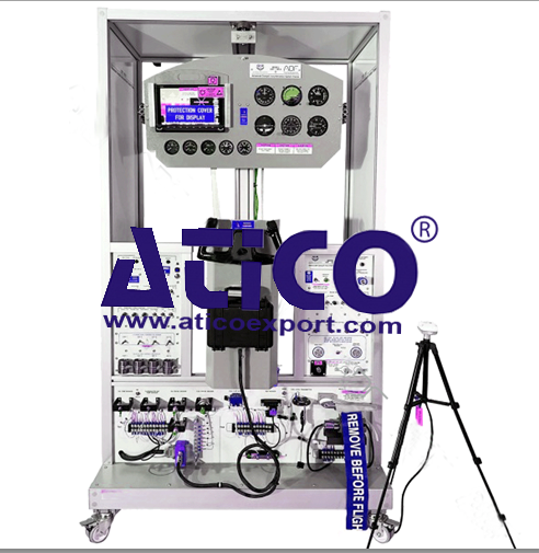
Features:
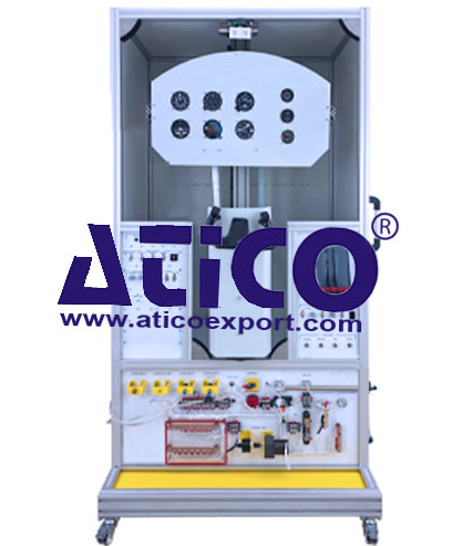
The system combines Cockpit analog flight instrumentation, primary flight instrumentation, systems instrumentation and engine instrumentation.
Trainer use the
latest in GPS and Digital ADAHRS (Air Data and Attitude Heading and Reference
Systems.
Air Data and
Attitude Heading and Reference Systems- provide highly accurate and reliable
referencing of position, rate, vector and acceleration data.
Three degrees
of freedom instrument panel permits full demonstration of attitude and
directional gyro functions.
Functional
engine monitoring system be connected to engine sensors.
All analog
instruments operate manually
Primary flight
display be mounted on a panel that can simulate roll, pitch, and yaw movements
controlled by a mechanism operated by a control yoke.
Components:
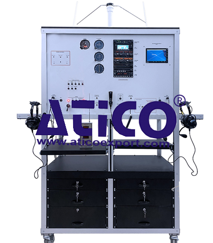
Smart PFD-MFD
Screen
Engine Data
Modules
Analog
instruments
Attitude Gyro
and Indicator
Directional
Gyro / Heading Indicator
Airspeed
Indicator
Altimeter
Vertical Speed
Indicator
Turn and Slip
Indicator
Fuel Temp/Press
Indicator
Oil Temp/Press
Indicators
Fuel Level
Indicator
MAP
RPM
Vacuum Gauge
Sensors:
Oil Temperature
Sensor
Carburetor Air
Temp Sensor
Manifold
Pressure Sensor
Fuel Level
Sensor
Oil Pressure
Sensor
Fuel Pressure
Sensor
Engine RPM
Sensor
Fuel Flow
Sensor
Ammeter Shunt
CHT
Thermocouples (Qty 4)
EGT
Thermocouples (Qty 4)
OAT Sensor
Pitot Tube
Static Port
Inductive sensor
Throttle Lever
Propeller Lever
Pitot-Static System:
Pressure Pump to Create Pitot Pressure
Vacuum Pump to
Create Static Pressure
Pitot Tube (not
operate)
Fuselage Static
Port (not operate)
Alternate
Static Port (not operate)
Static Source
Selector Switch (not operate)
Two Test Ports
for Pitot-Static Test Set
Power
Main Power
PDF
Tachometer
Turn Slip
Vacuum Pump
Contacts:
Pitot Heater
L/G
Taxi Light
Auxiliary
Flight Control:
Aileron Trim
Elevator Trim
Flap Position
Electronic Simulation of Sensors:
Oil Temperature
Manifold Pressure
Engine RPM
Oil Pressure
Fuel Level
Fuel Press
Sender Selector
Panel
Fuel System
Oil System
Vacuum Control
Panel
Static System
İnstrument
MAP
Fuel Flow
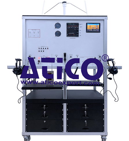
Smart PFD-MFD
Screen
NOT: Smart
PFD-MFD Screen brand/model and some technical specs can be change due to market
availability. (Dynon-Bendix-Garmin or similar)
Screen is very
bright and high-resolution driven by advanced graphics processors create highly
visible and readable display.
Display is 1280
x 800 pixel, 1200+ nit TFT active-matrix capacitive multi- touch LCD screen.
High-Definition
Touch Screen
Display
Connectors Specification
There are
37-Pin DIN Connector for the main wiring harness.
There are four
(4) RS-232 connector ports for connection to compatible equipment.
All serial
ports have configurable baud rates and data formats for use as general-purpose
inputs and output.
There is
minimum three (2) USB Connectors.
There is an
Ethernet Connector to be used to synchronize data between displays.
Displays
operate between 10- and 30-volts DC.
Display show
“engine instrument data”
Display show
“flight instrument data”
Screen
Dimensions
7.64″ Wide
5.59″ High
3.13″ Deep
Users should be
able to interact via the two knobs, two buttons integrated into the knobs, and
eight buttons along the bottom of the display’s bezel and via touch gestures on
the display screen itself.
Display have a
robust GPS moving map.
Display
backlighting is controlled by its ambient light sensor to actively adjust the
brightness based on the current lighting conditions or user should be able to
adjust the brightness by buttons.
The default
layout of screen shows below
PFD
MAP
ENGINE
Screen switch
into 100% window or 50%/50% split windows.
There is
Count-Up/Count-Down timer in the display.
PFD Page Layout
have at least the following:
Airspeed
Indicator
Ground Speed
(GS)
True Airspeed
(TAS)
Airspeed Bug
Airspeed Trend
Rate
Attitude
Indicator
Flight Path
Marker
Altimeter
Setting
Barometer (BARO)
Altitude Bug
Altitude Trend
Rate
Barometer
Setting, and Density Altitude.
Vertical Speed
Indicator
Vertical Speed
(VS) BUG.
Heading
Indicator/Directional Gyro
Heading (HDG)
BUG
Slip Ball
Angle of Attack
Indicator
OAT (Outside
air temperature)
Winds Aloft
magnitude and vector
Artificial
Horizon/Synthetic Vision
Menu Page have at least the following:
Six Pack
G-meter
Terrain Alert
Airport Flags
HSI SRC
Bugs
There is a
Six-Pack presentation options on the PFD.
Main Menu bar
are at the bottom of the screen and should include following functions:
NRST – Nearest:
FPL – Flight
Plan
INFO
MENU
Message (NO MSG
/ MESSAGE / CAUTION / WARNING)
KNOPs functions
have at least the following:
Adjust Bug
(HDG, ALT, etc.) or BARO value
Change Map
scale
Activate and/or
move cursor
Flight Data
Modules have at least the following:
All sensors
should be solid state.
Accelerometers,
which measure forces in all three directions
Rotational rate
sensors, which sense rotation about all three axes
Pressure
transducers for measuring air data
Magnetometers
on all three axes for measuring magnetic heading.
Engine Data Modules have at least the following:
These modules support popular four and six-cylinder engine installations and should measure a variety of engine and environmental parameters, such as:
RPM
Manifold
pressure
Oil temperature
Oil pressure
Exhaust gas
temperature (EGT)
Cylinder head
temperature (CHT)
Fuel levels for
multiple tanks
Voltage
Current
Fuel pressure
Fuel flow
Carburetor air
temperature
Coolant
pressure and temperature
Flap and trim
potentiometers
External
contacts
quick overview :
Features:
The system combines Cockpit analog flight instrumentation, primary flight instrumentation, systems instrumentation and engine instrumentation.
Trainer use the
latest in GPS and Digital ADAHRS (Air Data and Attitude Heading and Reference
Systems.
Air Data and
Attitude Heading and Reference Systems- provide highly accurate and reliable
referencing of position, rate, vector and acceleration data.
Three degrees
of freedom instrument panel permits full demonstration of attitude and
directional gyro functions.
Functional
engine monitoring system be connected to engine sensors.
All analog
instruments operate manually
Primary flight
display be mounted on a panel that can simulate roll, pitch, and yaw movements
controlled by a mechanism operated by a control yoke.
Components:
Smart PFD-MFD
Screen
Engine Data
Modules
Analog
instruments
Attitude Gyro
and Indicator
Directional
Gyro / Heading Indicator
Airspeed
Indicator
Altimeter
Vertical Speed
Indicator
Turn and Slip
Indicator
Fuel Temp/Press
Indicator
Oil Temp/Press
Indicators
Fuel Level
Indicator
MAP
RPM
Vacuum Gauge
Sensors:
Oil Temperature
Sensor
Carburetor Air
Temp Sensor
Manifold
Pressure Sensor
Fuel Level
Sensor
Oil Pressure
Sensor
Fuel Pressure
Sensor
Engine RPM
Sensor
Fuel Flow
Sensor
Ammeter Shunt
CHT
Thermocouples (Qty 4)
EGT
Thermocouples (Qty 4)
OAT Sensor
Pitot Tube
Static Port
Inductive sensor
Throttle Lever
Propeller Lever
Pitot-Static System:
Pressure Pump to Create Pitot Pressure
Vacuum Pump to
Create Static Pressure
Pitot Tube (not
operate)
Fuselage Static
Port (not operate)
Alternate
Static Port (not operate)
Static Source
Selector Switch (not operate)
Two Test Ports
for Pitot-Static Test Set
Power
Main Power
PDF
Tachometer
Turn Slip
Vacuum Pump
Contacts:
Pitot Heater
L/G
Taxi Light
Auxiliary
Flight Control:
Aileron Trim
Elevator Trim
Flap Position
Electronic Simulation of Sensors:
Oil Temperature
Manifold Pressure
Engine RPM
Oil Pressure
Fuel Level
Fuel Press
Sender Selector
Panel
Fuel System
Oil System
Vacuum Control
Panel
Static System
İnstrument
MAP
Fuel Flow
Smart PFD-MFD
Screen
NOT: Smart
PFD-MFD Screen brand/model and some technical specs can be change due to market
availability. (Dynon-Bendix-Garmin or similar)
Screen is very
bright and high-resolution driven by advanced graphics processors create highly
visible and readable display.
Display is 1280
x 800 pixel, 1200+ nit TFT active-matrix capacitive multi- touch LCD screen.
High-Definition
Touch Screen
Display
Connectors Specification
There are
37-Pin DIN Connector for the main wiring harness.
There are four
(4) RS-232 connector ports for connection to compatible equipment.
All serial
ports have configurable baud rates and data formats for use as general-purpose
inputs and output.
There is
minimum three (2) USB Connectors.
There is an
Ethernet Connector to be used to synchronize data between displays.
Displays
operate between 10- and 30-volts DC.
Display show
“engine instrument data”
Display show
“flight instrument data”
Screen
Dimensions
7.64″ Wide
5.59″ High
3.13″ Deep
Users should be
able to interact via the two knobs, two buttons integrated into the knobs, and
eight buttons along the bottom of the display’s bezel and via touch gestures on
the display screen itself.
Display have a
robust GPS moving map.
Display
backlighting is controlled by its ambient light sensor to actively adjust the
brightness based on the current lighting conditions or user should be able to
adjust the brightness by buttons.
The default
layout of screen shows below
PFD
MAP
ENGINE
Screen switch
into 100% window or 50%/50% split windows.
There is
Count-Up/Count-Down timer in the display.
PFD Page Layout
have at least the following:
Airspeed
Indicator
Ground Speed
(GS)
True Airspeed
(TAS)
Airspeed Bug
Airspeed Trend
Rate
Attitude
Indicator
Flight Path
Marker
Altimeter
Setting
Barometer (BARO)
Altitude Bug
Altitude Trend
Rate
Barometer
Setting, and Density Altitude.
Vertical Speed
Indicator
Vertical Speed
(VS) BUG.
Heading
Indicator/Directional Gyro
Heading (HDG)
BUG
Slip Ball
Angle of Attack
Indicator
OAT (Outside
air temperature)
Winds Aloft
magnitude and vector
Artificial
Horizon/Synthetic Vision
Menu Page have at least the following:
Six Pack
G-meter
Terrain Alert
Airport Flags
HSI SRC
Bugs
There is a
Six-Pack presentation options on the PFD.
Main Menu bar
are at the bottom of the screen and should include following functions:
NRST – Nearest:
FPL – Flight
Plan
INFO
MENU
Message (NO MSG
/ MESSAGE / CAUTION / WARNING)
KNOPs functions
have at least the following:
Adjust Bug
(HDG, ALT, etc.) or BARO value
Change Map
scale
Activate and/or
move cursor
Flight Data
Modules have at least the following:
All sensors
should be solid state.
Accelerometers,
which measure forces in all three directions
Rotational rate
sensors, which sense rotation about all three axes
Pressure
transducers for measuring air data
Magnetometers
on all three axes for measuring magnetic heading.
Engine Data Modules have at least the following:
These modules support popular four and six-cylinder engine installations and should measure a variety of engine and environmental parameters, such as:
RPM
Manifold
pressure
Oil temperature
Oil pressure
Exhaust gas
temperature (EGT)
Cylinder head
temperature (CHT)
Fuel levels for
multiple tanks
Voltage
Current
Fuel pressure
Fuel flow
Carburetor air
temperature
Coolant
pressure and temperature
Flap and trim
potentiometers
External
contacts
Product
Reviews
add Review
reviews
No Review Yet.
Related
Products
Sediment Transport Demonstration Channel
Specification: A transparent, inclinable flow channel thr...
Advanced Cockpit Instrumentation Traine...
Features: The system combines Cockpit analog flight inst...
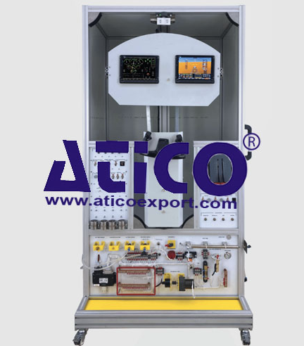
Features: The system combines primary flight instrumentati...
Features: The system combine primary flight instrument...
Analogue Cockpit Instrumentation System...
Features: The system combines Cockpit analog flight...
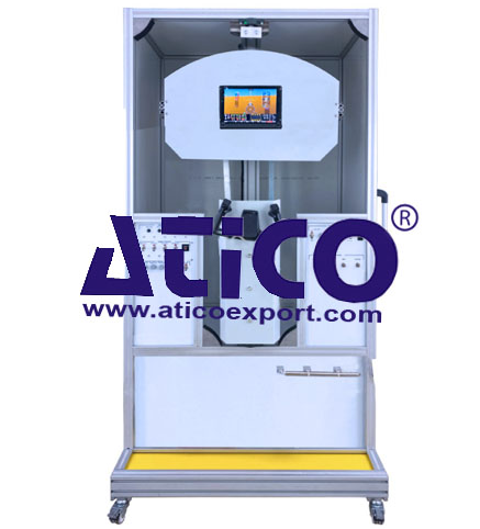
Features: Components: Screen System Two PFD/MFD...
Features: The system combines Navigation (ADF-DME-VOR-IL...
Features: The system combines Navigation (ADF-DME-VOR-IL...
Copyrights © 2025 All Rights Reserved by Atico
Product
Reviews
add Review
reviews
No Review Yet.