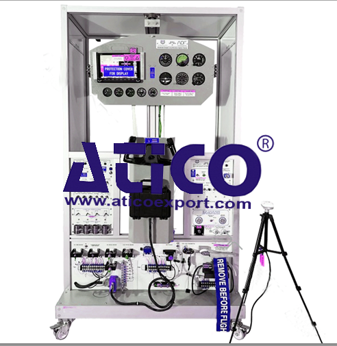
Avionics System Trainer
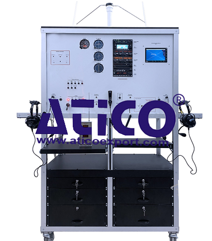
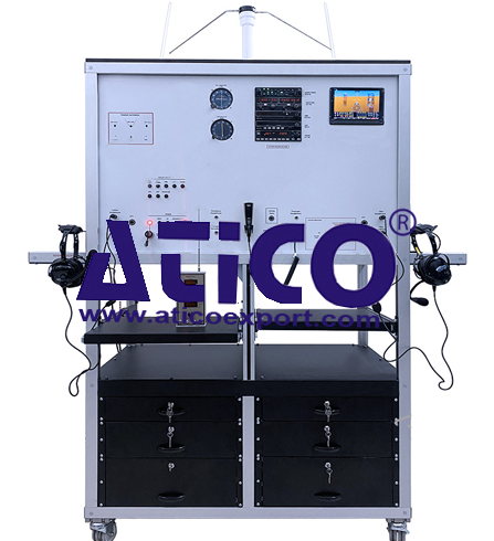
Categories: Aviation Maintenance Training EquipmentFeatures: The system combines Navigation (ADF-DME-VOR-ILS-GPS-XPDR) instrumentation, Communication (VHF) instrumentation, and navigational information. NAV system testing Comm System Test...


Product
Description
Features:
The system
combines Navigation (ADF-DME-VOR-ILS-GPS-XPDR) instrumentation, Communication
(VHF) instrumentation, and navigational information.
- NAV system testing
- Comm System Testing
- Indication Testing
- Encoder Altimeter Testing
- Altitude simulation
- Altimeter and Transponder run in sync
- TXPDR Ident
- DME Channel selection
- Six (6) metal drawers.
- All required cabling, coupler, splitter and socket
- Instructor’s Panel for fault insertion.
- Extension cable for GPS Antenna
- Tripod stand for mounting GPS Antenna
- The system mounted on a metal/aluminum mobile stand.
- Metal/aluminum frame with 4 wheels. 2 of 4 wheels are
lockable
- Delivered fully assembled tested and ready to operate
Components:
- Two (2) pieces Nav/Com Radio (VOR/ ILS)
- Two (2) pieces Nav Indicators (Analog or Digital)
- GPS (Global Positioning System)
- ADF (Automatic Direction Finder)
- ADF Indicator
- ILS (Instrument Landing System)
- DME (Distance Measuring Equipment)
- Transponder
- Marker Beacon
- Altitude Encoder
- Intercom System
- Two Pilot Headsets
- Dynamic Microphone
- Altimeter
- Vacuum Pump
- Dc Power Box
- Circuit Breaker
- Antennas
- VOR/LOC antenna
- ADF antenna
- Marker-Beacon antenna
- GS antenna
- VHF-COM antenna
- TRANSPONDER antenna
- All antennas cable
Components Technical
- NAV/COM Device General
- NAV/COMM Transceiver
- 200-channel NAV receiver
- Built-in VOR Converter
- Maximum 25 kHz channel spacing
- Frequency (COM) 118.000 to 136.975
- Nav frequency 108.00 MHz to 117.95
MHz in 50 kHz spacing
- VOR/LOC converter
- Input voltage 28 VDC
- Built-in VOR/Localizer converter
- Flip-Flop frequencies
- Volume control
- Frequency memory and recall
- Display
- Frequency stability: ±0.0015%
- Original installation manual.
- NAV INDICATOR Device General
- Navigation Indicator containing
VOR/LOC left-right needle
- To-From Indicator
- VOR/LOC Warning Flag
- OBS
- Integral VOR/LOC Converter
- At least one of them Glideslope
Deviation needle
- Internally lighted
- Metal bezel with glass lens
- Used with nav-receiver
- Typical VOR Accuracy; (VOR) Bearing
error less than 1.7 degrees. Full scale deflection for 10 deg. course
error.
- Converter Inputs: .5vrms +-10% ARINC
phasing (VOR Composite Input); 100k ohms (Input Impedance)
- Course Datum Synchro Output:
393mV/degree, 1 deg. Accuracy Typical
- Typical Accuracy (Loc): (Loc) Centering
error less than 3uA. Three fifths deflection for 4dB tone ratio
- CONVERTER OUTPUT DRIVE CAPABILITY:
Five 1K loads 150 uA full scale (VOR/LOC Deviation); Two 200 ohm,
200-0-200uA loads (TO/FROM); Five 1K ohm, 0-260uA loads (VOR/LOC Warning
Flag)
- Original installation manual.
- Transponder Device General
- Transmitter Frequency; 1090 MHz +-3
MHz
- Receiver Sensitivity: -73dBm
(nominal); -69dBm (min. for 90% reply)
- Mode C Capability: Accepts standard
ICAO Altitude Transmission Code digitizer output, reporting in 100 ft.
increments from -1000 ft. throughout operating range
- Input voltage 28 VDC
- 4096 discrete codes
- Backlight labels and knobs
- CLR button
- VFR button
- IDT button
- Numeric Buttons (0-1-2-3-4-5-6-7)
- KNOP(OFF-SBY-TST-ON-ALT)
- Code window
- Original installation manual.
- DME Device General
- 200-channel receiver
- CHANNELING SOURCES: External control
head providing BCD code, 2×5 code, slip code, or serial code
- RMT/FREQ/GS-T mode
- DME two concentric freq knop
- Freq Display
- Original installation manual.
- ADF Device General
- FREQUENCY RANGE: 200KHz to 1799KHz
in 1 KHz increments
- BEARING ACCURACY: +- 3 degrees from
70 uV/m to 0.5 V/m RF input signal level
- Receiver sensitivity: 150uV/m max
for s+n/n = 6dB
- Receiver Selectivity: 6dB bandwidth:
+-2 KHz max off center frequency; 80dB bandwidth: +-7 KHz max off center
frequency
- POWER REQUIREMENTS: 11 to 33 VDC –
12watt
- ADF button
- BFO button
- FRQ button
- FLT/ET button
- SET/RST button
- VOL/Off knop
- Freq display
- Original installation manual.
- ADF Indicator General
- Single needle ADF indicator for use
with ADF receiver
- ADF BEARING INPUT: DC sine and
cosine voltages, +-3.0VDC max across each winding
- POWER REQUIREMENTS: Compass Card
Drive: 12VDC at 0.12A
- Lighting: 14VDC at 0.16A or 28VDC at
0.08A
- GPS Device General
- Power 10-33 Volt DC
- Operate up to 50.000 feet
- Color IFR GPS with moving map
- Comprehensive aeronautical database
including airports, VORs, NDBs, intersections, and special-use airspace
- Automatic “vector to final” approach
capability
- Dedicated “Range” and “Map” menu
buttons facilitate map access and tailoring
- Dedicated “Procedures” button
simplifies loading of approaches and arrival / departure procedures
- Provides map presentation of other
non-GPS approaches (including ILS approaches) for greater situational
awareness
- Aviation Map General
- 7” screen
- At least 9 watts
- Operate 24 volts
- Should have a tripod for GPS
- Audio Panel General
- Audio Inputs;
- Impedance: 600 ohms
- input: 5 Vrms
- Isolation: 60 dB minimum
- Bandwidth: 100 Hz to 6.5 kHz
- Transceiver: 3 (including TEL)
- Receiver: 5 (NAV1, NAV2, AUX1,
AUX2, AUX3)
- Alerts: 4 (unswitched)
- Telephone input: 1
- Intercom Functions;
- Positions: 6 (pilot, copilot, 4
passengers)
- Volume control: 2 (pilot,
copilot/passengers)
- VOX: Automatic (1 per MIC input)
- Modes: Pilot, crew, all
- MIC impedance: 150 ohms
- MIC Bias: 11 VDC through 470 ohms
- Keyed ICS: Configurable
- Music functions;
- Inputs: 2 (independent from
Bluetooth audio)
- Impedance: 600 ohms (differential)
- input: 3.0 Vrms
- Gain: +24 dB Max/-96dB min
- Input level: < 200 mVrms at max
gain for full power out 3dB@1kHz Bandwidth 20 Hz to 20 kHz
- Distortion: < 0.1% THD+N typical
at full power over full bandwidth
- Muting: Selectable and configurable
- Volume control: Knob controlled
(pilot and copilot/passenger)
- Headphone Outputs
- Output amplifiers: 3 Stereo (pilot,
copilot, passenger)
- Output power: 65 mW into 150 Ohms
Pilot and Copilot, 260 mW into 37.5 Ohms passenger
- Distortion: < 3% THD+N at 10%
Power, < 10% THD+N at full power
- Frequency response: 20 Hz to 20 kHz
- Impedance rated: 150 Ohm
pilot/copilot, 37.5 Ohm Passenger (4-150 Ohm headsets)
- Impedance supported: 150 to >
600 Ohm
- Speaker;
- Outputs: 1
- 28 Volt: 10 Watt into 4 Ohm; 7 Watt
into 8 Ohm
- 14 Volt: 3 Watt into 4 Ohm 3dB@1kHz
Bandwidth 350 Hz to 6.5 kHz
- Distortion: < 10% THD+N at full
power, < 3% THD+N at 10% power
- Headsets
- 24 dB NRR hearing protection3.5mm
Music input port
- EM56 noise reflective cup mic
- Clear Hear performance audio
speakers
- Foam Fit comfort ear seals
- Deep Pocket ear canals
- Wind block foam mic muff
- Stainless steel adjustable headband
- DYNAMIC MICROPHONE
- Impedance: 50-600 ohms.
- Includes: 5 ft. coiled cord with
right-angle plug and hanger bracket.
- Right angle plug
- Hanger bracket
- Antennas
- VOR/LOC antenna
- ADF antenna
- Marker-Beacon antenna
- GS antenna
- Vhf-Com antenna (2 pieces)
- Transponder antenna
- All antennas cables
quick overview :
Features:
The system
combines Navigation (ADF-DME-VOR-ILS-GPS-XPDR) instrumentation, Communication
(VHF) instrumentation, and navigational information.
- NAV system testing
- Comm System Testing
- Indication Testing
- Encoder Altimeter Testing
- Altitude simulation
- Altimeter and Transponder run in sync
- TXPDR Ident
- DME Channel selection
- Six (6) metal drawers.
- All required cabling, coupler, splitter and socket
- Instructor’s Panel for fault insertion.
- Extension cable for GPS Antenna
- Tripod stand for mounting GPS Antenna
- The system mounted on a metal/aluminum mobile stand.
- Metal/aluminum frame with 4 wheels. 2 of 4 wheels are
lockable
- Delivered fully assembled tested and ready to operate
Components:
- Two (2) pieces Nav/Com Radio (VOR/ ILS)
- Two (2) pieces Nav Indicators (Analog or Digital)
- GPS (Global Positioning System)
- ADF (Automatic Direction Finder)
- ADF Indicator
- ILS (Instrument Landing System)
- DME (Distance Measuring Equipment)
- Transponder
- Marker Beacon
- Altitude Encoder
- Intercom System
- Two Pilot Headsets
- Dynamic Microphone
- Altimeter
- Vacuum Pump
- Dc Power Box
- Circuit Breaker
- Antennas
- VOR/LOC antenna
- ADF antenna
- Marker-Beacon antenna
- GS antenna
- VHF-COM antenna
- TRANSPONDER antenna
- All antennas cable
Components Technical
- NAV/COM Device General
- NAV/COMM Transceiver
- 200-channel NAV receiver
- Built-in VOR Converter
- Maximum 25 kHz channel spacing
- Frequency (COM) 118.000 to 136.975
- Nav frequency 108.00 MHz to 117.95
MHz in 50 kHz spacing
- VOR/LOC converter
- Input voltage 28 VDC
- Built-in VOR/Localizer converter
- Flip-Flop frequencies
- Volume control
- Frequency memory and recall
- Display
- Frequency stability: ±0.0015%
- Original installation manual.
- NAV INDICATOR Device General
- Navigation Indicator containing
VOR/LOC left-right needle
- To-From Indicator
- VOR/LOC Warning Flag
- OBS
- Integral VOR/LOC Converter
- At least one of them Glideslope
Deviation needle
- Internally lighted
- Metal bezel with glass lens
- Used with nav-receiver
- Typical VOR Accuracy; (VOR) Bearing
error less than 1.7 degrees. Full scale deflection for 10 deg. course
error.
- Converter Inputs: .5vrms +-10% ARINC
phasing (VOR Composite Input); 100k ohms (Input Impedance)
- Course Datum Synchro Output:
393mV/degree, 1 deg. Accuracy Typical
- Typical Accuracy (Loc): (Loc) Centering
error less than 3uA. Three fifths deflection for 4dB tone ratio
- CONVERTER OUTPUT DRIVE CAPABILITY:
Five 1K loads 150 uA full scale (VOR/LOC Deviation); Two 200 ohm,
200-0-200uA loads (TO/FROM); Five 1K ohm, 0-260uA loads (VOR/LOC Warning
Flag)
- Original installation manual.
- Transponder Device General
- Transmitter Frequency; 1090 MHz +-3
MHz
- Receiver Sensitivity: -73dBm
(nominal); -69dBm (min. for 90% reply)
- Mode C Capability: Accepts standard
ICAO Altitude Transmission Code digitizer output, reporting in 100 ft.
increments from -1000 ft. throughout operating range
- Input voltage 28 VDC
- 4096 discrete codes
- Backlight labels and knobs
- CLR button
- VFR button
- IDT button
- Numeric Buttons (0-1-2-3-4-5-6-7)
- KNOP(OFF-SBY-TST-ON-ALT)
- Code window
- Original installation manual.
- DME Device General
- 200-channel receiver
- CHANNELING SOURCES: External control
head providing BCD code, 2×5 code, slip code, or serial code
- RMT/FREQ/GS-T mode
- DME two concentric freq knop
- Freq Display
- Original installation manual.
- ADF Device General
- FREQUENCY RANGE: 200KHz to 1799KHz
in 1 KHz increments
- BEARING ACCURACY: +- 3 degrees from
70 uV/m to 0.5 V/m RF input signal level
- Receiver sensitivity: 150uV/m max
for s+n/n = 6dB
- Receiver Selectivity: 6dB bandwidth:
+-2 KHz max off center frequency; 80dB bandwidth: +-7 KHz max off center
frequency
- POWER REQUIREMENTS: 11 to 33 VDC –
12watt
- ADF button
- BFO button
- FRQ button
- FLT/ET button
- SET/RST button
- VOL/Off knop
- Freq display
- Original installation manual.
- ADF Indicator General
- Single needle ADF indicator for use
with ADF receiver
- ADF BEARING INPUT: DC sine and
cosine voltages, +-3.0VDC max across each winding
- POWER REQUIREMENTS: Compass Card
Drive: 12VDC at 0.12A
- Lighting: 14VDC at 0.16A or 28VDC at
0.08A
- GPS Device General
- Power 10-33 Volt DC
- Operate up to 50.000 feet
- Color IFR GPS with moving map
- Comprehensive aeronautical database
including airports, VORs, NDBs, intersections, and special-use airspace
- Automatic “vector to final” approach
capability
- Dedicated “Range” and “Map” menu
buttons facilitate map access and tailoring
- Dedicated “Procedures” button
simplifies loading of approaches and arrival / departure procedures
- Provides map presentation of other
non-GPS approaches (including ILS approaches) for greater situational
awareness
- Aviation Map General
- 7” screen
- At least 9 watts
- Operate 24 volts
- Should have a tripod for GPS
- Audio Panel General
- Audio Inputs;
- Impedance: 600 ohms
- input: 5 Vrms
- Isolation: 60 dB minimum
- Bandwidth: 100 Hz to 6.5 kHz
- Transceiver: 3 (including TEL)
- Receiver: 5 (NAV1, NAV2, AUX1,
AUX2, AUX3)
- Alerts: 4 (unswitched)
- Telephone input: 1
- Intercom Functions;
- Positions: 6 (pilot, copilot, 4
passengers)
- Volume control: 2 (pilot,
copilot/passengers)
- VOX: Automatic (1 per MIC input)
- Modes: Pilot, crew, all
- MIC impedance: 150 ohms
- MIC Bias: 11 VDC through 470 ohms
- Keyed ICS: Configurable
- Music functions;
- Inputs: 2 (independent from
Bluetooth audio)
- Impedance: 600 ohms (differential)
- input: 3.0 Vrms
- Gain: +24 dB Max/-96dB min
- Input level: < 200 mVrms at max
gain for full power out 3dB@1kHz Bandwidth 20 Hz to 20 kHz
- Distortion: < 0.1% THD+N typical
at full power over full bandwidth
- Muting: Selectable and configurable
- Volume control: Knob controlled
(pilot and copilot/passenger)
- Headphone Outputs
- Output amplifiers: 3 Stereo (pilot,
copilot, passenger)
- Output power: 65 mW into 150 Ohms
Pilot and Copilot, 260 mW into 37.5 Ohms passenger
- Distortion: < 3% THD+N at 10%
Power, < 10% THD+N at full power
- Frequency response: 20 Hz to 20 kHz
- Impedance rated: 150 Ohm
pilot/copilot, 37.5 Ohm Passenger (4-150 Ohm headsets)
- Impedance supported: 150 to >
600 Ohm
- Speaker;
- Outputs: 1
- 28 Volt: 10 Watt into 4 Ohm; 7 Watt
into 8 Ohm
- 14 Volt: 3 Watt into 4 Ohm 3dB@1kHz
Bandwidth 350 Hz to 6.5 kHz
- Distortion: < 10% THD+N at full
power, < 3% THD+N at 10% power
- Headsets
- 24 dB NRR hearing protection3.5mm
Music input port
- EM56 noise reflective cup mic
- Clear Hear performance audio
speakers
- Foam Fit comfort ear seals
- Deep Pocket ear canals
- Wind block foam mic muff
- Stainless steel adjustable headband
- DYNAMIC MICROPHONE
- Impedance: 50-600 ohms.
- Includes: 5 ft. coiled cord with
right-angle plug and hanger bracket.
- Right angle plug
- Hanger bracket
- Antennas
- VOR/LOC antenna
- ADF antenna
- Marker-Beacon antenna
- GS antenna
- Vhf-Com antenna (2 pieces)
- Transponder antenna
- All antennas cables
Product
Reviews
add Review
reviews
No Review Yet.
Related
Products
Sediment Transport Demonstration Channel
Specification: A transparent, inclinable flow channel thr...
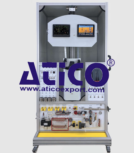
Advanced Cockpit Instrumentation Traine...
Features: The system combines Cockpit analog flight inst...
Features: The system combines primary flight instrumentati...
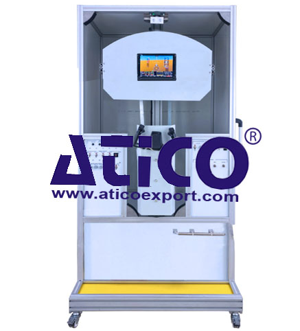
Features: The system combine primary flight instrument...
Analogue Cockpit Instrumentation System...
Features: The system combines Cockpit analog flight...
Features: Components: Screen System Two PFD/MFD...
Features: The system combines Navigation (ADF-DME-VOR-IL...
Features: The system combines Navigation (ADF-DME-VOR-IL...
Copyrights © 2025 All Rights Reserved by Atico
Product
Reviews
add Review
reviews
No Review Yet.