

Autopilot / Automatic Flight Controls Trainer
Categories: Aviation Maintenance Training EquipmentFeatures: Indicators operate in sync with auto-pilot system Position controlled by yoke and rudder system. Automatic/Motorized Yoke System Yoke automatically/motorized moves...





Product
Description
Features:
- Indicators operate in sync with auto-pilot system
- Position controlled by yoke and rudder
system.
- Automatic/Motorized Yoke System
- Yoke automatically/motorized moves
in two axis with data from autopilot
computer. It performs automatic positioning according to the position of the airplane. - Rudder Pedal System
- Rudder surface moves in one axis
with data from rudder pedals manual inputs from user. It performs
automatic positioning according to the position of the airplane.
- Throttle and mixture levers operation.
- Yoke and rudder pedals can move the control surfaces
of the in manual mode.
- Autopilot computer can move the control surfaces of autopilot modes.
- Servos operate in sync with auto-pilot and
yoke/rudder pedal.
- 3 DOF (2 axis DOF + 1 DOF system)
- Heading Feed Back
- Altitude Feed Back
- Engine start process
- Auto pilot function
- Flight director function
- The automatically calibrated to runway
position when the trainer is turned on.
- Instructor’s fault and scenario control window
- The system mounted on a metal/aluminum mobile stand.
- Metal/aluminum frame with 4 wheels. 2 of 4 wheels are
lockable
Components:
- Size is minimum
1400mmx1300mm
- Color is white.
- Aileron and elevator are different
color.
- Aileron and Elevator can move.
- Aileron and elevator operate in sync
with auto-pilot and yoke.
- 4 auto-pilot servos on the (aileron, elevator, rudder, pitch trim).
- Pitch / Yaw / Roll servos / pitch
trim servo
- There are 2 limit switches in servo.
- Servos operates in sync with
auto-pilot and yoke.
- DOF system operates in sync with
autopilot (aileron and elevator) and yoke.
- One beacon light at the nose section of the model
- Two(2) PFD/MFD system with bezels
- PFD can be used as engine
instruments incase of simulated failure
- Bezels Generals
- All buttons, switches and knobs can
operate
- Dual control Navigation(NAV) Knop
- For example, dual COMM rotary knob
have three functions, outer ring should tune UHF/VHF frequency in MHz,
inner ring should tune the frequency in KHz and pressing this knob
toggles the tuning cursor between the COM1 and COM2 fields.
- Bezels have backlight function for
night flights.
- Screens are 2048×1536 resolution
touch screens.
- PFD/MFD system should include
minimum below features
- Auto-Pilot.
- Flight director.
- Pitch modes.
- Pitch Hold.
- Altitude Hold.
- Vertical Speed.
- Flight Level Change.
- Vertical Path Tracking.
- VNV Target Altitude Capture.
- Glidepath.
- Glideslope: Yes.
- Roll modes.
- Roll Hold.
- Heading Select.
- Navigation.
- Backcourse.
- Approach
- Flight Plan
- Invert Flight Plan
- Parallel Track
- Create ATK Offset Waypoint
- Direct-to
- Terminal Procedures
- User defined holding patterns
- Navigation database
- Inset map: Zoom in/out, browsing,
partly de-clutter, topo and terrain. No traffic, storm scope, NEXRAD
radar Synthetic Vision as an In-App Purchase item
- VOR/ILS course select, VOR/Waypoint bearing indicator, CDI indicator, etc.
- Wind, Bearing1/2, HSI format, Alt
unit, Standard baro
- DME source selection.
- Transponder settings.
- Timer and references (V speeds and
minimums).
- Advisory and alerts.
- Automatic Magnetic variation.
- Global navigation database and topo
data
- Engine status
- Functional “Map Setup”
- Flight plans storing/editing.
- Terminal procedures
- User waypoint creating/editing.
- User defined holding patterns
- PFD/MFD Controls
- AP Key – Engages/disengages the
autopilot and flight director. Pressing the AP Key activates the flight
director and engages the autopilot in the default pitch axis and roll
axis modes. Pressing the AP Key again disengages the autopilot and
deactivates the flight director. - HDG Key – Selects/deselects Heading
Select Mode.
- NAV Key – Selects/deselects
Navigation Mode.
- APR Key – Selects/deselects Approach
Mode.
- VS Key – Selects/deselects Vertical
Speed Mode.
- FLC Key – Selects/deselects Flight
Level Change Mode.
- FD Key – Activates/deactivates the
flight director only. Pressing the FD Key turns on the flight director in
the default pitch axis and roll axis modes. Pressing the FD Key again
deactivates the flight director and removes the command bars, unless the
autopilot is engaged. If the autopilot is engaged, the FD Key is
disabled.
- ALT Key – Selects/deselects Altitude
Hold Mode.
- VNV Key – Selects/deselects Vertical
Navigation Mode.
- BC Key – Selects/deselects Back
Course Mode.
- NOSE UP/NOSE DN Keys – Controls the
active pitch reference for the Pitch Hold, Vertical Speed, and Flight
Level Change modes.
- NAV VOL/ID Knob – Controls the NAV
audio level. Press to toggle the Morse code identifier ON and OFF.
- NAV Frequency Transfer Key Transfers
the standby and active NAV frequencies.
- Dual NAV Knob – Tunes the MHz (large
knob) and kHz (small knob) standby frequencies for the NAV receiver.
Press to toggle the tuning cursor (light blue box) between the NAV1 and
NAV2 fields.
- Heading Knob – Turn to manually
select a heading on the HSI. When pressed, it synchronizes the heading
bug with the compass lubber line. Selected Heading provides the heading
reference to the Flight Director while operating in Heading Select mode.
- Joystick – Changes the map range
(distance top to bottom of map display) when rotated. Activates the map
pointer when pressed.
- CRS/BARO Knob – The large knob sets
the altimeter barometric pressure and the small knob adjusts the course.
The course is only adjustable when the HSIisin VOR1, VOR2, or
OBS/SUSP mode
- Dual COM Knob – Tunes the MHz (large
knob) and kHz (small knob) standby frequencies for the COM transceiver.
- COM Frequency Transfer Key –
Transfers the standby and active COM frequencies. Pressing and holding
this key for two seconds automatically tunes the emergency frequency
(121.5 MHz) in the active frequency field.
- COM VOL/SQ Knob – Controls COM audio
level.
- Direct-to Key – Allows the user to
enter a destination waypoint and establish a direct course to the
selected destination (specified by the identifier, chosen from the active
route, or taken from the map pointer position).
- FPL Key – Displays the active Flight
Plan Page for creating and editing the active flight plan, or for
accessing stored flight plans.
- Dual FMS Knob – Press to turn the
selection cursor ON/OFF.
- PROC Key – Selects approaches,
departures and arrivals from the flight plan. If a flight plan is used,
available procedures for the departure and/or arrival airport are
automatically suggested. If a flight plan is not used, the desired
airport and the desired procedure may be selected. This key selects IFR
departure procedures (DPs), arrival procedures (STARs) and approaches
(IAPs) from the database and loads them into the active flight plan
- ENT Key – Accepts a menu selection
or data entry. This key is used to approve an operation or complete data
entry. It is also used to confirm selections and information entries.
- Dual ALT Knob – Sets the selected
altitude in the box located above the Altimeter. The large knob selects
the thousands (500m for metric), while the small knob selects the
hundreds (50m for metric). Altitude Select is used by the Automatic
Flight Control System in certain modes, in addition to the standard G1000
Altitude Alerter function.
- All flight indicators operate in sync with auto-pilot
system
- Position controlled by yoke.
- Yoke moves the control surfaces
- The rudder pedal mechanism is metal.
- Rudder pedal move the control surfaces
- Active throttle control.
- Active mixture control.
- The Trainer master power and switch panel.
- Air / ground scenario choosing switch
- Engine Start,
- Auto-Pilot circuit breaker,
- Servo control switch
- Beacon circuit breaker,
- Circuit breaker lockout,
quick overview :
Features:
- Indicators operate in sync with auto-pilot system
- Position controlled by yoke and rudder
system.
- Automatic/Motorized Yoke System
- Yoke automatically/motorized moves
in two axis with data from autopilot
computer. It performs automatic positioning according to the position of the airplane. - Rudder Pedal System
- Rudder surface moves in one axis
with data from rudder pedals manual inputs from user. It performs
automatic positioning according to the position of the airplane.
- Throttle and mixture levers operation.
- Yoke and rudder pedals can move the control surfaces
of the in manual mode.
- Autopilot computer can move the control surfaces of autopilot modes.
- Servos operate in sync with auto-pilot and
yoke/rudder pedal.
- 3 DOF (2 axis DOF + 1 DOF system)
- Heading Feed Back
- Altitude Feed Back
- Engine start process
- Auto pilot function
- Flight director function
- The automatically calibrated to runway
position when the trainer is turned on.
- Instructor’s fault and scenario control window
- The system mounted on a metal/aluminum mobile stand.
- Metal/aluminum frame with 4 wheels. 2 of 4 wheels are
lockable
Components:
- Size is minimum
1400mmx1300mm
- Color is white.
- Aileron and elevator are different
color.
- Aileron and Elevator can move.
- Aileron and elevator operate in sync
with auto-pilot and yoke.
- 4 auto-pilot servos on the (aileron, elevator, rudder, pitch trim).
- Pitch / Yaw / Roll servos / pitch
trim servo
- There are 2 limit switches in servo.
- Servos operates in sync with
auto-pilot and yoke.
- DOF system operates in sync with
autopilot (aileron and elevator) and yoke.
- One beacon light at the nose section of the model
- Two(2) PFD/MFD system with bezels
- PFD can be used as engine
instruments incase of simulated failure
- Bezels Generals
- All buttons, switches and knobs can
operate
- Dual control Navigation(NAV) Knop
- For example, dual COMM rotary knob
have three functions, outer ring should tune UHF/VHF frequency in MHz,
inner ring should tune the frequency in KHz and pressing this knob
toggles the tuning cursor between the COM1 and COM2 fields.
- Bezels have backlight function for
night flights.
- Screens are 2048×1536 resolution
touch screens.
- PFD/MFD system should include
minimum below features
- Auto-Pilot.
- Flight director.
- Pitch modes.
- Pitch Hold.
- Altitude Hold.
- Vertical Speed.
- Flight Level Change.
- Vertical Path Tracking.
- VNV Target Altitude Capture.
- Glidepath.
- Glideslope: Yes.
- Roll modes.
- Roll Hold.
- Heading Select.
- Navigation.
- Backcourse.
- Approach
- Flight Plan
- Invert Flight Plan
- Parallel Track
- Create ATK Offset Waypoint
- Direct-to
- Terminal Procedures
- User defined holding patterns
- Navigation database
- Inset map: Zoom in/out, browsing,
partly de-clutter, topo and terrain. No traffic, storm scope, NEXRAD
radar Synthetic Vision as an In-App Purchase item
- VOR/ILS course select, VOR/Waypoint bearing indicator, CDI indicator, etc.
- Wind, Bearing1/2, HSI format, Alt
unit, Standard baro
- DME source selection.
- Transponder settings.
- Timer and references (V speeds and
minimums).
- Advisory and alerts.
- Automatic Magnetic variation.
- Global navigation database and topo
data
- Engine status
- Functional “Map Setup”
- Flight plans storing/editing.
- Terminal procedures
- User waypoint creating/editing.
- User defined holding patterns
- PFD/MFD Controls
- AP Key – Engages/disengages the
autopilot and flight director. Pressing the AP Key activates the flight
director and engages the autopilot in the default pitch axis and roll
axis modes. Pressing the AP Key again disengages the autopilot and
deactivates the flight director. - HDG Key – Selects/deselects Heading
Select Mode.
- NAV Key – Selects/deselects
Navigation Mode.
- APR Key – Selects/deselects Approach
Mode.
- VS Key – Selects/deselects Vertical
Speed Mode.
- FLC Key – Selects/deselects Flight
Level Change Mode.
- FD Key – Activates/deactivates the
flight director only. Pressing the FD Key turns on the flight director in
the default pitch axis and roll axis modes. Pressing the FD Key again
deactivates the flight director and removes the command bars, unless the
autopilot is engaged. If the autopilot is engaged, the FD Key is
disabled.
- ALT Key – Selects/deselects Altitude
Hold Mode.
- VNV Key – Selects/deselects Vertical
Navigation Mode.
- BC Key – Selects/deselects Back
Course Mode.
- NOSE UP/NOSE DN Keys – Controls the
active pitch reference for the Pitch Hold, Vertical Speed, and Flight
Level Change modes.
- NAV VOL/ID Knob – Controls the NAV
audio level. Press to toggle the Morse code identifier ON and OFF.
- NAV Frequency Transfer Key Transfers
the standby and active NAV frequencies.
- Dual NAV Knob – Tunes the MHz (large
knob) and kHz (small knob) standby frequencies for the NAV receiver.
Press to toggle the tuning cursor (light blue box) between the NAV1 and
NAV2 fields.
- Heading Knob – Turn to manually
select a heading on the HSI. When pressed, it synchronizes the heading
bug with the compass lubber line. Selected Heading provides the heading
reference to the Flight Director while operating in Heading Select mode.
- Joystick – Changes the map range
(distance top to bottom of map display) when rotated. Activates the map
pointer when pressed.
- CRS/BARO Knob – The large knob sets
the altimeter barometric pressure and the small knob adjusts the course.
The course is only adjustable when the HSIisin VOR1, VOR2, or
OBS/SUSP mode
- Dual COM Knob – Tunes the MHz (large
knob) and kHz (small knob) standby frequencies for the COM transceiver.
- COM Frequency Transfer Key –
Transfers the standby and active COM frequencies. Pressing and holding
this key for two seconds automatically tunes the emergency frequency
(121.5 MHz) in the active frequency field.
- COM VOL/SQ Knob – Controls COM audio
level.
- Direct-to Key – Allows the user to
enter a destination waypoint and establish a direct course to the
selected destination (specified by the identifier, chosen from the active
route, or taken from the map pointer position).
- FPL Key – Displays the active Flight
Plan Page for creating and editing the active flight plan, or for
accessing stored flight plans.
- Dual FMS Knob – Press to turn the
selection cursor ON/OFF.
- PROC Key – Selects approaches,
departures and arrivals from the flight plan. If a flight plan is used,
available procedures for the departure and/or arrival airport are
automatically suggested. If a flight plan is not used, the desired
airport and the desired procedure may be selected. This key selects IFR
departure procedures (DPs), arrival procedures (STARs) and approaches
(IAPs) from the database and loads them into the active flight plan
- ENT Key – Accepts a menu selection
or data entry. This key is used to approve an operation or complete data
entry. It is also used to confirm selections and information entries.
- Dual ALT Knob – Sets the selected
altitude in the box located above the Altimeter. The large knob selects
the thousands (500m for metric), while the small knob selects the
hundreds (50m for metric). Altitude Select is used by the Automatic
Flight Control System in certain modes, in addition to the standard G1000
Altitude Alerter function.
- All flight indicators operate in sync with auto-pilot
system
- Position controlled by yoke.
- Yoke moves the control surfaces
- The rudder pedal mechanism is metal.
- Rudder pedal move the control surfaces
- Active throttle control.
- Active mixture control.
- The Trainer master power and switch panel.
- Air / ground scenario choosing switch
- Engine Start,
- Auto-Pilot circuit breaker,
- Servo control switch
- Beacon circuit breaker,
- Circuit breaker lockout,
Product
Reviews
add Review
reviews
No Review Yet.
Related
Products
Sediment Transport Demonstration Channel
Specification: A transparent, inclinable flow channel thr...
Advanced Cockpit Instrumentation Traine...
Features: The system combines Cockpit analog flight inst...
Features: The system combines primary flight instrumentati...
Features: The system combine primary flight instrument...

Analogue Cockpit Instrumentation System...
Features: The system combines Cockpit analog flight...
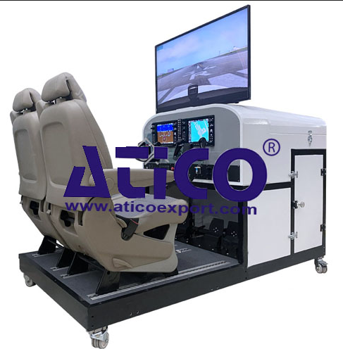
Features: Components: Screen System Two PFD/MFD...
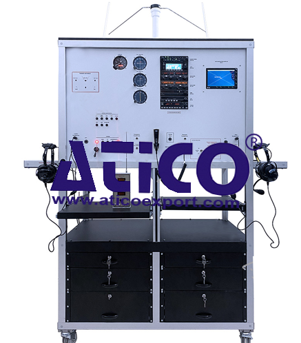
Features: The system combines Navigation (ADF-DME-VOR-IL...
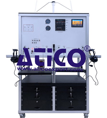
Features: The system combines Navigation (ADF-DME-VOR-IL...
Product
Reviews
add Review
reviews
No Review Yet.