

Avionics and Cockpit Instrumentation System Trainer
Categories: Aviation Maintenance Training EquipmentFeatures: The system combine Navigation(ADF-DME-VOR-ILS-GPS-XPDR) instrumentation, Communication(VHF) instrumentation, navigational information. primary flight instrumentation, aircr...





Product
Description
Features:
- The system combine Navigation(ADF-DME-VOR-ILS-GPS-XPDR)
instrumentation, Communication(VHF) instrumentation, navigational
information. primary flight instrumentation, aircraft systems
instrumentation and engine instrumentation.
- Roll, pitch and yaw motions can be operated from the
side yoke to be able to demonstrate aircraft attitude and directional gyro
functions.
- Functional engine monitoring system be connected to
engine sensors.
- Primary flight display be mounted on a panel that can
simulate roll, pitch, and yaw movements controlled by a mechanism operated
by a control yoke.
- Provision of engine sensor simulation.
- Pitot-static system to conduct pitot static system
checks for digital instrument at the trainer.
- NAV system testing
- Comm System Testing
- Indication Testing
- Encoder Altimeter Testing
- Altitude simulation
- Altimeter and Transponder run in sync
- TXPDR Ident
- DME Channel selection
- 6(six) metal drawers.
- All required cabling, coupler ,splitter and socket
- Extension cable for GPS Antenna
- Tripod stand for mounting GPS Antenna
- The system mounted on a metal/aluminum mobile stand.
- Metal/aluminum frame with 4 wheels. 2 of 4 wheels are
lockable
Components:
- Smart PFD-MFD Screen
- Engine Data Modules
- Nav/Com Radio ( Vor/ ILS )
- Nav Indicators ( Analog )
- GPS (Global Positioning System )
- ADF (Automatic Direction Finder )
- ADF Indicator
- ILS (Instrument Landing System )
- DME (Distance Measuring Equipment)
- Transponder
- Marker Beacon
- Altitude Encoder
- Intercom System
- Two Pilot Headsets
- Dynamic Microphone
- Vacuum Pump
- Dc Power Box
- Aircraft circuit breaker
- Antennas
- VOR/LOC antenna
- ADF antenna
- Marker-Beacon antenna
- GS antenna
- VHF-COM antenna
- TRANSPONDER antenna
- All antennas cables
- Sensors:
- Oil Temperature Sensor
- Carburetor Air Temp Sensor
- Manifold Pressure Sensor
- Fuel Level Sensor
- Oil Pressure Sensor
- Fuel Pressure Sensor
- Engine RPM Sensor
- Fuel Flow Sensor
- Ammeter Shunt
- CHT Thermocouples (Qty 4)
- EGT Thermocouples (Qty 4)
- OAT Sensor
- Pitot Tube
- Static Port
- Inductive sensor
- Throttle Lever
- Pitot-Static System:
- Pressure Pump to Create Pitot
Pressure
- Vacuum Pump to Create Static
Pressure
- Pitot Tube (not operate)
- Fuselage Static Port (not operate)
- Alternate Static Port(not operate)
- Static Source Selector Switch (not
operate)
- Two Test Ports for Pitot-Static Test
Set
- Contacs:
- Pitot Heater
- L/G
- Taxi Light
- Electronic Simulation of Sensors:
- Oil Temperature Manifold Pressure
- Engine RPM
- Oil Pressure
- Fuel Level
- Fuel Press
Components
Technical
- NAV/COM Device
- NAV/COMM Transceiver
- 200-channel NAV receiver
- Built-in VOR Converter
- Maximum 25 kHz channel spacing
- Frequency (COM) 118.000 to 136.975
- Nav frequency 108.00 MHz to 117.95
MHz in 50 kHz spacing
- VOR/LOC converter
- Input voltage 28 VDC
- Built-in VOR/Localizer converter
- Flip-flop frequencies
- Volume control
- Frequency memory and recall
- Display
- Original installation manual.
- NAV INDICATOR Device
- Navigation Indicator containing
VOR/LOC left-right needle
- To-From Indicator
- VOR/LOC Warning Flag
- OBS
- Integral VOR/LOC Converter
- Glideslope Deviation needle
- Metal bezel with glass lens
- Original installation manual.
- Transponder Device
- Transmitter Frequency; 1090 MHz +-3
MHz
- Receiver Sensitivity: -73dBm
(nominal); -69dBm (min. for 90% reply)
- Mode A,C
- Input voltage 14/28 VDC
- DME Device
- 200-channel receiver
- CHANNELING SOURCES: External control
head providing BCD code, 2×5 code, slip code, or serial code
- RMT/FREQ/GS-T mode
- DME two concentric freq knop
- Freq Display
- Original installation manual.
- ADF Device
- FREQUENCY RANGE: 200KHz to 1799KHz
in 1 KHz increments
- BEARING ACCURACY: +- 3 degrees from
70 uV/m to 0.5 V/m RF input signal level
- Receiver sensitivity: 150uV/m max
for s+n/n = 6dB
- Receiver Selectivity: 6dB bandwidth:
+-2 KHz max off center frequency; 80dB bandwidth: +-7 KHz max off center
frequency
- POWER REQUIREMENTS: 11 to 33 VDC –
12watt
- ADF button
- BFO button
- FRQ button
- FLT/ET button
- SET/RST button
- VOL/Off knop
- Freq display
- Original installation manual.
- ADF Indicator
- Single needle ADF indicator for use
with ADF receiver
- Adf Bearing Input: DC sine and
cosine voltages, +-3.0VDC max across each winding
- Power Requirements: Compass Card
Drive: 12VDC at 0.12A
- Lighting: 14VDC at 0.16A or 28VDC at
0.08A
- Audio Panel
- Audio Inputs;
- Impedance: 600 ohms
- Max input: 5 Vrms
- Isolation: 60 dB minimum
- Bandwidth: 100 Hz to 6.5 kHz
- Transceiver: 3 (including TEL)
- Receiver: 5 (NAV1, NAV2, AUX1,
AUX2, AUX3)
- Alerts: 4 (unswitched)
- Telephone input: 1
- Intercom Functions;
- Positions: 6 (pilot, copilot, 4
passengers)
- Volume control: 2 (pilot,
copilot/passengers)
- VOX: Automatic (1 per MIC input)
- Modes: Pilot, crew, all
- MIC impedance: 150 ohms
- MIC Bias: 11 VDC through 470 ohms
- Keyed ICS: Configurable
- Music functions;
- Inputs: 2 (independent from
Bluetooth audio)
- Impedance: 600 ohms (differential)
- input: 3.0 Vrms
- Gain: +24 dB Max/-96dB min
- Input level: < 200 mVrms at max
gain for full power out 3dB@1kHz Bandwidth 20 Hz to 20 kHz
- Distortion: < 0.1% THD+N typical
at full power over full bandwidth
- Muting: Selectable and configurable
- Volume control: Knob controlled
(pilot and copilot/passenger)
- Headphone Outputs
- Output amplifiers: 3 Stereo (pilot,
copilot, passenger)
- Output power: 65 mW into 150 Ohms
Pilot and Copilot, 260 mW into 37.5 Ohms passenger
- Distortion: < 3% THD+N at 10%
Power, < 10% THD+N at full power
- Frequency response: 20 Hz to 20 kHz
- Impedance rated: 150 Ohm
pilot/copilot, 37.5 Ohm Passenger (4-150 Ohm headsets)
- Impedance supported: 150 to >
600 Ohm
- Speaker;
- Outputs: 1
- 28 Volt: 10 Watt into 4 Ohm; 7 Watt
into 8 Ohm
- 14 Volt: 3 Watt into 4 Ohm 3dB@1kHz
Bandwidth 350 Hz to 6.5 kHz
- Distortion: < 10% THD+N at full
power, < 3% THD+N at 10% power
- Smart PFD-MFD Screen
- NOTE: Smart PFD-MFD Screen
brand/model and some technical specs can be change due to market
availability. ( Dynon-Bendix-Garmin or similar )
- Screen is very bright and
high-resolution driven by advanced graphics processors create highly
visible and readable display.
- Display is 1280 x 800 pixel, 1200+
nit TFT active-matrix capacitive multi- touch LCD screen.
- High-Definition Touch Screen
- Display Connectors Specification
- There are 37-Pin DIN Connector for
the main wiring harness.
- There are four (4) RS-232 connector
ports for connection to compatible
equipment. - All serial ports have configurable
baud rates and data formats for use as general-purpose inputs and
output.
- There are minimum three (2) USB
Connectors.
- There is an Ethernet Connector to
be used to synchronize data between
displays. - Displays operate between 10- and
30-volts DC.
- Display show “engine instrument
data”
- Display show “flight instrument
data”
- Screen Dimensions
- 7.64” Wide
- 5.59” High
- 3.13” Deep
- Users are able to interact via the
two knobs, two buttons integrated into the knobs, and eight buttons along
the bottom of the display’s bezel and via touch gestures on the display
screen itself.
- Display have a robust GPS moving
map.
- Display back-lighting is controlled
by its ambient light sensor to actively adjust the brightness based on
the current lighting conditions or user is able to adjust the brightness
by buttons.
- The default layout of screen show
below
- Pfd
- Map
- Engine
- Screen switch into 100% window or
50%/50% split windows.
- There is Count-Up/Count-Down timer
in the display.
- PFD Page Layout have at least the
following:
- Airspeed Indicator
- Ground Speed (GS)
- True Airspeed (TAS)
- Airspeed Bug
- Airspeed Trend Rate
- Attitude Indicator
- Flight Path Marker
- Altimeter
- Setting Barometer (BARO)
- Altitude Bug
- Altitude Trend Rate
- Barometer Setting, and Density
Altitude.
- Vertical Speed Indicator
- Vertical Speed (VS) BUG.
- Heading Indicator/Directional Gyro
- Heading (HDG) BUG
- Slip Ball
- Angle of Attack Indicator
- OAT(Outside air temperature)
- Winds Aloft magnitude and vector
- Artificial Horizon/Synthetic Vision
- Menu Page have at least the
following:
- Six Pack
- G-meter
- Terrain Alert
- Airport Flags
- HSI SRC
- Bugs
- There is a Six-Pack presentation
options on the PFD
- Main Menu bar are at the bottom of
the screen and include following functions:
- NRST – Nearest:
- Info page
- FPL – Flight Plan
- INFO
- MENU
- Message( NO MSG / Message / Caution
/ Warning )
- Knob’s functions have at least the
following:
- Adjust Bug (HDG, ALT, etc.)or BARO
value
- Change Map scale
- Activate and/or move cursor
- Flight Data Modules have at least
the following:
- All sensors are solid state.
- Accelerometers, which measure forces
in all three directions
- Rotational rate sensors, which sense
rotation about all three axes
- Pressure transducers for measuring
air data
- Magnetometers on all three axes for
measuring magnetic heading.
- Engine Data Modules have at least
the following:
- These modules support popular four
and six-cylinder engine installations and measure a variety of engine
and environmental parameters, such as:
- RPM
- Manifold pressure
- Oil temperature
- Oil pressure
- Exhaust gas temperature (EGT)
- Cylinder head temperature (CHT)
- Fuel levels for multiple tanks
- Voltage
- Current
- Fuel pressure
- Fuel flow
- Carburetor air temperature
- Coolant pressure and temperature
- Flap and trim potentiometers
- External contacts
- Fuel Computer
- Pitch Trim Indicator
- Roll Trim Indicators
- Flap Indicator
- Headsets
- 24 dB NRR hearing protection
- 3.5mm Music input port
- EM56 noise reflective cup mic
- Clear Hear performance audio
speakers
- Foam Fit comfort ear seals
- Deep Pocket ear canals
- Wind block foam mic muff
- Stainless steel adjustable headband
- DYNAMIC MICROPHONE
- Impedance: 50-600 ohms.
- Includes: 5 ft. coiled cord with
right-angle plug and hanger bracket.
- Right angle plug
- Hanger bracket
quick overview :
Features:
- The system combine Navigation(ADF-DME-VOR-ILS-GPS-XPDR)
instrumentation, Communication(VHF) instrumentation, navigational
information. primary flight instrumentation, aircraft systems
instrumentation and engine instrumentation.
- Roll, pitch and yaw motions can be operated from the
side yoke to be able to demonstrate aircraft attitude and directional gyro
functions.
- Functional engine monitoring system be connected to
engine sensors.
- Primary flight display be mounted on a panel that can
simulate roll, pitch, and yaw movements controlled by a mechanism operated
by a control yoke.
- Provision of engine sensor simulation.
- Pitot-static system to conduct pitot static system
checks for digital instrument at the trainer.
- NAV system testing
- Comm System Testing
- Indication Testing
- Encoder Altimeter Testing
- Altitude simulation
- Altimeter and Transponder run in sync
- TXPDR Ident
- DME Channel selection
- 6(six) metal drawers.
- All required cabling, coupler ,splitter and socket
- Extension cable for GPS Antenna
- Tripod stand for mounting GPS Antenna
- The system mounted on a metal/aluminum mobile stand.
- Metal/aluminum frame with 4 wheels. 2 of 4 wheels are
lockable
Components:
- Smart PFD-MFD Screen
- Engine Data Modules
- Nav/Com Radio ( Vor/ ILS )
- Nav Indicators ( Analog )
- GPS (Global Positioning System )
- ADF (Automatic Direction Finder )
- ADF Indicator
- ILS (Instrument Landing System )
- DME (Distance Measuring Equipment)
- Transponder
- Marker Beacon
- Altitude Encoder
- Intercom System
- Two Pilot Headsets
- Dynamic Microphone
- Vacuum Pump
- Dc Power Box
- Aircraft circuit breaker
- Antennas
- VOR/LOC antenna
- ADF antenna
- Marker-Beacon antenna
- GS antenna
- VHF-COM antenna
- TRANSPONDER antenna
- All antennas cables
- Sensors:
- Oil Temperature Sensor
- Carburetor Air Temp Sensor
- Manifold Pressure Sensor
- Fuel Level Sensor
- Oil Pressure Sensor
- Fuel Pressure Sensor
- Engine RPM Sensor
- Fuel Flow Sensor
- Ammeter Shunt
- CHT Thermocouples (Qty 4)
- EGT Thermocouples (Qty 4)
- OAT Sensor
- Pitot Tube
- Static Port
- Inductive sensor
- Throttle Lever
- Pitot-Static System:
- Pressure Pump to Create Pitot
Pressure
- Vacuum Pump to Create Static
Pressure
- Pitot Tube (not operate)
- Fuselage Static Port (not operate)
- Alternate Static Port(not operate)
- Static Source Selector Switch (not
operate)
- Two Test Ports for Pitot-Static Test
Set
- Contacs:
- Pitot Heater
- L/G
- Taxi Light
- Electronic Simulation of Sensors:
- Oil Temperature Manifold Pressure
- Engine RPM
- Oil Pressure
- Fuel Level
- Fuel Press
Components
Technical
- NAV/COM Device
- NAV/COMM Transceiver
- 200-channel NAV receiver
- Built-in VOR Converter
- Maximum 25 kHz channel spacing
- Frequency (COM) 118.000 to 136.975
- Nav frequency 108.00 MHz to 117.95
MHz in 50 kHz spacing
- VOR/LOC converter
- Input voltage 28 VDC
- Built-in VOR/Localizer converter
- Flip-flop frequencies
- Volume control
- Frequency memory and recall
- Display
- Original installation manual.
- NAV INDICATOR Device
- Navigation Indicator containing
VOR/LOC left-right needle
- To-From Indicator
- VOR/LOC Warning Flag
- OBS
- Integral VOR/LOC Converter
- Glideslope Deviation needle
- Metal bezel with glass lens
- Original installation manual.
- Transponder Device
- Transmitter Frequency; 1090 MHz +-3
MHz
- Receiver Sensitivity: -73dBm
(nominal); -69dBm (min. for 90% reply)
- Mode A,C
- Input voltage 14/28 VDC
- DME Device
- 200-channel receiver
- CHANNELING SOURCES: External control
head providing BCD code, 2×5 code, slip code, or serial code
- RMT/FREQ/GS-T mode
- DME two concentric freq knop
- Freq Display
- Original installation manual.
- ADF Device
- FREQUENCY RANGE: 200KHz to 1799KHz
in 1 KHz increments
- BEARING ACCURACY: +- 3 degrees from
70 uV/m to 0.5 V/m RF input signal level
- Receiver sensitivity: 150uV/m max
for s+n/n = 6dB
- Receiver Selectivity: 6dB bandwidth:
+-2 KHz max off center frequency; 80dB bandwidth: +-7 KHz max off center
frequency
- POWER REQUIREMENTS: 11 to 33 VDC –
12watt
- ADF button
- BFO button
- FRQ button
- FLT/ET button
- SET/RST button
- VOL/Off knop
- Freq display
- Original installation manual.
- ADF Indicator
- Single needle ADF indicator for use
with ADF receiver
- Adf Bearing Input: DC sine and
cosine voltages, +-3.0VDC max across each winding
- Power Requirements: Compass Card
Drive: 12VDC at 0.12A
- Lighting: 14VDC at 0.16A or 28VDC at
0.08A
- Audio Panel
- Audio Inputs;
- Impedance: 600 ohms
- Max input: 5 Vrms
- Isolation: 60 dB minimum
- Bandwidth: 100 Hz to 6.5 kHz
- Transceiver: 3 (including TEL)
- Receiver: 5 (NAV1, NAV2, AUX1,
AUX2, AUX3)
- Alerts: 4 (unswitched)
- Telephone input: 1
- Intercom Functions;
- Positions: 6 (pilot, copilot, 4
passengers)
- Volume control: 2 (pilot,
copilot/passengers)
- VOX: Automatic (1 per MIC input)
- Modes: Pilot, crew, all
- MIC impedance: 150 ohms
- MIC Bias: 11 VDC through 470 ohms
- Keyed ICS: Configurable
- Music functions;
- Inputs: 2 (independent from
Bluetooth audio)
- Impedance: 600 ohms (differential)
- input: 3.0 Vrms
- Gain: +24 dB Max/-96dB min
- Input level: < 200 mVrms at max
gain for full power out 3dB@1kHz Bandwidth 20 Hz to 20 kHz
- Distortion: < 0.1% THD+N typical
at full power over full bandwidth
- Muting: Selectable and configurable
- Volume control: Knob controlled
(pilot and copilot/passenger)
- Headphone Outputs
- Output amplifiers: 3 Stereo (pilot,
copilot, passenger)
- Output power: 65 mW into 150 Ohms
Pilot and Copilot, 260 mW into 37.5 Ohms passenger
- Distortion: < 3% THD+N at 10%
Power, < 10% THD+N at full power
- Frequency response: 20 Hz to 20 kHz
- Impedance rated: 150 Ohm
pilot/copilot, 37.5 Ohm Passenger (4-150 Ohm headsets)
- Impedance supported: 150 to >
600 Ohm
- Speaker;
- Outputs: 1
- 28 Volt: 10 Watt into 4 Ohm; 7 Watt
into 8 Ohm
- 14 Volt: 3 Watt into 4 Ohm 3dB@1kHz
Bandwidth 350 Hz to 6.5 kHz
- Distortion: < 10% THD+N at full
power, < 3% THD+N at 10% power
- Smart PFD-MFD Screen
- NOTE: Smart PFD-MFD Screen
brand/model and some technical specs can be change due to market
availability. ( Dynon-Bendix-Garmin or similar )
- Screen is very bright and
high-resolution driven by advanced graphics processors create highly
visible and readable display.
- Display is 1280 x 800 pixel, 1200+
nit TFT active-matrix capacitive multi- touch LCD screen.
- High-Definition Touch Screen
- Display Connectors Specification
- There are 37-Pin DIN Connector for
the main wiring harness.
- There are four (4) RS-232 connector
ports for connection to compatible
equipment. - All serial ports have configurable
baud rates and data formats for use as general-purpose inputs and
output.
- There are minimum three (2) USB
Connectors.
- There is an Ethernet Connector to
be used to synchronize data between
displays. - Displays operate between 10- and
30-volts DC.
- Display show “engine instrument
data”
- Display show “flight instrument
data”
- Screen Dimensions
- 7.64” Wide
- 5.59” High
- 3.13” Deep
- Users are able to interact via the
two knobs, two buttons integrated into the knobs, and eight buttons along
the bottom of the display’s bezel and via touch gestures on the display
screen itself.
- Display have a robust GPS moving
map.
- Display back-lighting is controlled
by its ambient light sensor to actively adjust the brightness based on
the current lighting conditions or user is able to adjust the brightness
by buttons.
- The default layout of screen show
below
- Pfd
- Map
- Engine
- Screen switch into 100% window or
50%/50% split windows.
- There is Count-Up/Count-Down timer
in the display.
- PFD Page Layout have at least the
following:
- Airspeed Indicator
- Ground Speed (GS)
- True Airspeed (TAS)
- Airspeed Bug
- Airspeed Trend Rate
- Attitude Indicator
- Flight Path Marker
- Altimeter
- Setting Barometer (BARO)
- Altitude Bug
- Altitude Trend Rate
- Barometer Setting, and Density
Altitude.
- Vertical Speed Indicator
- Vertical Speed (VS) BUG.
- Heading Indicator/Directional Gyro
- Heading (HDG) BUG
- Slip Ball
- Angle of Attack Indicator
- OAT(Outside air temperature)
- Winds Aloft magnitude and vector
- Artificial Horizon/Synthetic Vision
- Menu Page have at least the
following:
- Six Pack
- G-meter
- Terrain Alert
- Airport Flags
- HSI SRC
- Bugs
- There is a Six-Pack presentation
options on the PFD
- Main Menu bar are at the bottom of
the screen and include following functions:
- NRST – Nearest:
- Info page
- FPL – Flight Plan
- INFO
- MENU
- Message( NO MSG / Message / Caution
/ Warning )
- Knob’s functions have at least the
following:
- Adjust Bug (HDG, ALT, etc.)or BARO
value
- Change Map scale
- Activate and/or move cursor
- Flight Data Modules have at least
the following:
- All sensors are solid state.
- Accelerometers, which measure forces
in all three directions
- Rotational rate sensors, which sense
rotation about all three axes
- Pressure transducers for measuring
air data
- Magnetometers on all three axes for
measuring magnetic heading.
- Engine Data Modules have at least
the following:
- These modules support popular four
and six-cylinder engine installations and measure a variety of engine
and environmental parameters, such as:
- RPM
- Manifold pressure
- Oil temperature
- Oil pressure
- Exhaust gas temperature (EGT)
- Cylinder head temperature (CHT)
- Fuel levels for multiple tanks
- Voltage
- Current
- Fuel pressure
- Fuel flow
- Carburetor air temperature
- Coolant pressure and temperature
- Flap and trim potentiometers
- External contacts
- Fuel Computer
- Pitch Trim Indicator
- Roll Trim Indicators
- Flap Indicator
- Headsets
- 24 dB NRR hearing protection
- 3.5mm Music input port
- EM56 noise reflective cup mic
- Clear Hear performance audio
speakers
- Foam Fit comfort ear seals
- Deep Pocket ear canals
- Wind block foam mic muff
- Stainless steel adjustable headband
- DYNAMIC MICROPHONE
- Impedance: 50-600 ohms.
- Includes: 5 ft. coiled cord with
right-angle plug and hanger bracket.
- Right angle plug
- Hanger bracket
Product
Reviews
add Review
reviews
No Review Yet.
Related
Products

Sediment Transport Demonstration Channel
Specification: A transparent, inclinable flow channel thr...
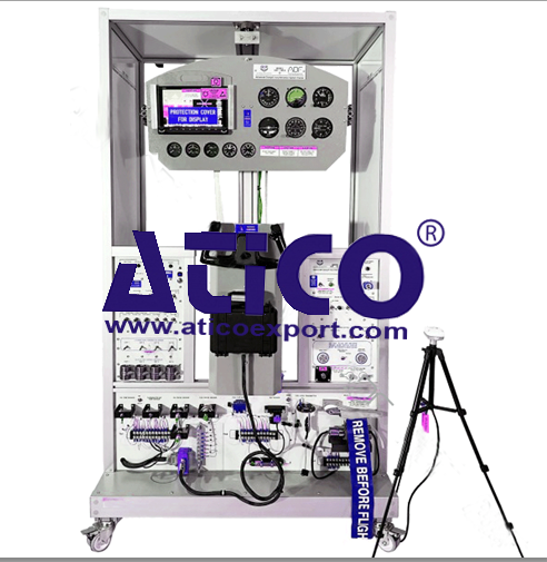
Advanced Cockpit Instrumentation Traine...
Features: The system combines Cockpit analog flight inst...
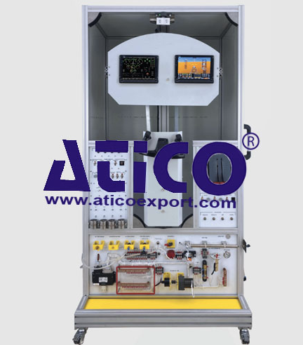
Features: The system combines primary flight instrumentati...
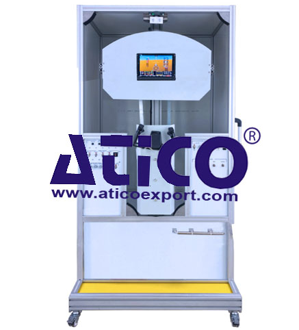
Features: The system combine primary flight instrument...
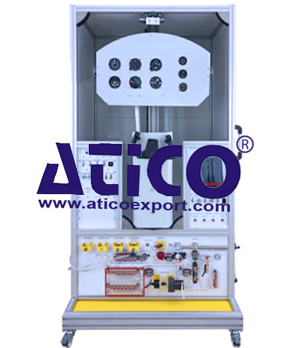
Analogue Cockpit Instrumentation System...
Features: The system combines Cockpit analog flight...
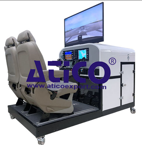
Features: Components: Screen System Two PFD/MFD...
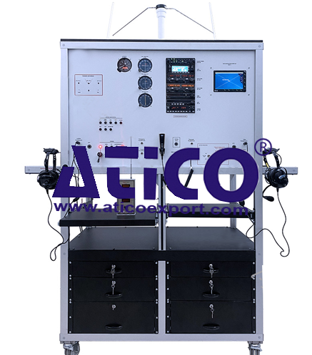
Features: The system combines Navigation (ADF-DME-VOR-IL...
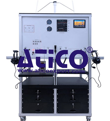
Features: The system combines Navigation (ADF-DME-VOR-IL...
Product
Reviews
add Review
reviews
No Review Yet.