quick overview :
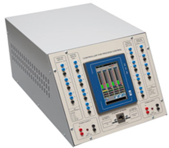
As with the present generation of PID controllers, the Four Loops PID Digital Controller has a structure based on a high performance microcontroller, analog inputs and outputs, programming of the regulation functions and serial interface for the communication with Personal Computers. The programming of the main parameters of the process control is carried out locally through the touch screen display. The controller can find immediate application to the control of various processes (temperature, pressure, flow rate and level) since it is designed to interface with those modules. It is provided with an Ethernet interface in order to be connected to a Personal Computer for data visualization and control. The main function of the regulator is to control and monitor the process continuously according to the programmed regulation algorithm. The regulator controls 4 auto-tuning regulation loops. The parameters for the P- proportional, D- derivative and Iintegrative regulation are set via the touch screen display or
via the PC. The high resolution display shows the numerical or graphic trend of the variables during the regulation (Set point, Regulated quantity, Error…).
TRAINING PROGRAM:
The equipment allows a wide range of educational applications such as:
• Analyzing the structure of a digital process regulator
• Programming the functions of the regulator;
• Analyzing the parameters: proportional, derivative and integrative coefficient;
• Analyzing the analog I/O signals and the connections with the process regulation;
• Applying algorithms to the functional programming of a digital process control
TECHNICAL SPECIFICATIONS:
• Front screen in isolating material with screen-printed diagrams and internal components
• Power supply unit 24 Vdc / 2 A with electronic protection against overload and short circuit
• Power supply unit 10 Vdc / 0.5 A with electronic protection against overload and short circuit
• 4 different regulation techniques:
- Multi Loops (1 to 4 loops)
- Ratio
- Cascade
- Override
When selecting a technique, the system automatically sets the corresponding parameters and gives some I/O specific functions.
• Color graphic TFT touch 4.3” display (480 x 272 pixels / colors: 16 M)
• Auto-tuning
• Alarm configuration page
• Alarm history
• Parameter page of the selected loop
• Trend page of the selected loop
• Parameter page of the analog inputs
• Parameter page of the analog outputs
• Parameter page of the digital I/O
• Status and forcing of I/O
• Time register
• Ethernet switch: on board
• Ø 2 mm jacks for instruments for connecting inputs and outputs to external devices.
Analog inputs
• 6 Voltage / current sortable analog inputs
• Voltage range: 0÷1 V / 0÷5 V / 1÷5 V / 0÷10 V
• Current Range: 0÷20 mA / 4÷20 mA
Digital inputs
• 8 optocoupled Auxiliary ON/OFF inputs (0-24 Vdc)
Set Point
• Local setting via the touch screen display
Analog outputs
• 4 voltage / current sortable analog outputs
• Voltage range: -10 V÷ +10 V / -20 V÷ +20 V / 0÷10 V
• Current Range: 4÷20 mA
Digital outputs
• 8 digital outputs 24 Vdc - 0.5 A
Communication
• 1 Ethernet interface for parameterization / supervision via PC of the regulator with Modbus TCP/IP protocol.
On board characteristics / functions
• High resolution color display
• Pages organized in a menu
• Visualizing the regulated figures in real-time
• Managing bar graphs, trends, alarms
• Optional use of password
• Power supply: 110/230 Vac 50 Hz single-phase


Product
Reviews
add Review
reviews
No Review Yet.