.png)
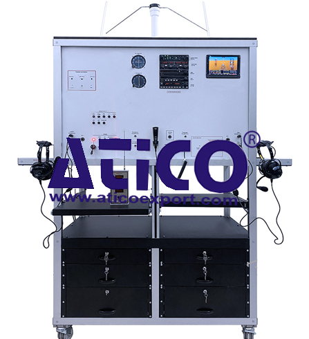
Hydraulic Landing Gear System Trainer (Module)
Categories: Aviation Maintenance Training EquipmentFeatures: Understanding fundamentals of aircraft hydraulic landing gear system and its components. Some of Trainer Functions Landing gear extension functions Landing gear retrac...


Product
Description
Features:
- Understanding fundamentals of aircraft hydraulic
landing gear system and its components.
- Some of Trainer Functions
- Landing gear extension functions
- Landing gear retraction functions
- Speed brake lever functions
- Flap lever functions
- Brake functions
- Park brake functions
- Hydraulic power functions
- Accumulator functions
- Emergency hand pump functions
- Pumps fault functions
- ECAM functions
- Single chime functions
- Master caution functions
- Master warning functions
- Check valves functions
- Some of Trainer Processes
- Landing gear extension test process
- Landing gear retraction test process
- Hydraulic system functional test
process
- Hydraulic system leak test process
- Hand pump test process
- Accumulator test process
- ECAM test process
- Emergency system test process
- Hydraulic Flap System
- Brake System
- Aircraft Wheel System
- Hydraulic System Control
- Lower ECAM (on the main unit)
- Master Caution System
- Aural warning Horn Panel System
- Hydraulic Landing Gear Trainer able to display the
landing gear operating system of a regular aircraft.
- Digital sensor data and switch states used in the
set.
- Throttle lever with associated components complete
the warning circuit of gear up warning horn.
- The accumulator and the hand pump be able to control
the landing gear.
- Wirings on the trainer are connected via terminals.
- Wires should have clear identification labels for
each wire.
- All wires should be coded and labeled for
troubleshooting.
- The system mounted on a metal/aluminum mobile stand.
- Metal/aluminum frame with 4 wheels. 2 of 4 wheels are
lockable.
- Delivered fully assembled tested and ready to operate
- Colored Ultraviolet printing method on aluminum
composite pane
Components:
- Electrically Driven Hydraulic Pump
- Hydraulics Filter
- Flap/Aileron control solenoid
- Emergency Hand Pump
- Hydraulic Fluid Reservoir
- Hydraulic Accumulator with automatic filling system
- Hydraulic System analog pressure gauge
- Valve pressure sender
- Hydraulic System Pressure sender
- Hydraulically Operated Landing Gear Mechanism
- Drain Valve
- Hydraulic Actuating Cylinder for Landing gear
- Hydraulic Actuating Cylinder for Landing gear door
- Check valve
- Hydraulic System analog pressure gauge
- Hydraulic System Pressure sender
- Brake pressure gauge
- Hydraulic Sequencing System and operate
- Hydraulic Flap System
- Hydraulic flap Actuating
- Flap Position Sensors
- Flap control switch
- Cutaway or Mock-up Flap
- Aircraft Tire Assembly (6 or 8 inch)
- Aircraft Tire
- Aircraft Wheel
- Aircraft Brake disk
- Aircraft Brake Plate
- Aircraft Brake caliber
- Hydraulic Brake Components
- Aircraft Brake master cylinder
- Park brake
- Brake Fluid Reservoir
- Aircraft Brake Pedal
- Brake Hose
- Throttle Lever (TQ)
- Control Panel
- Circuit brakers
- Aircraft Circuit breaker lockout
- Lockable Landing gear control lever
- Power Panel
- Aircraft Landing gear control panel
- Landing gear status lamp
- Lockable Flap control panel/lever
(pullable)
- Lockable speed brake control
panel/lever (push able)
- Landing Gear door control lamp
- Energy Lamp
- Lower EICAS or ECAM (10 inch on the main unit)
- Landing gear position
- Landing door position
- Pressure gauge
- Sensor’s status
- Landing gear system control
- Throttle Lever Position
- Speed brake position
quick overview :
Features:
- Understanding fundamentals of aircraft hydraulic
landing gear system and its components.
- Some of Trainer Functions
- Landing gear extension functions
- Landing gear retraction functions
- Speed brake lever functions
- Flap lever functions
- Brake functions
- Park brake functions
- Hydraulic power functions
- Accumulator functions
- Emergency hand pump functions
- Pumps fault functions
- ECAM functions
- Single chime functions
- Master caution functions
- Master warning functions
- Check valves functions
- Some of Trainer Processes
- Landing gear extension test process
- Landing gear retraction test process
- Hydraulic system functional test
process
- Hydraulic system leak test process
- Hand pump test process
- Accumulator test process
- ECAM test process
- Emergency system test process
- Hydraulic Flap System
- Brake System
- Aircraft Wheel System
- Hydraulic System Control
- Lower ECAM (on the main unit)
- Master Caution System
- Aural warning Horn Panel System
- Hydraulic Landing Gear Trainer able to display the
landing gear operating system of a regular aircraft.
- Digital sensor data and switch states used in the
set.
- Throttle lever with associated components complete
the warning circuit of gear up warning horn.
- The accumulator and the hand pump be able to control
the landing gear.
- Wirings on the trainer are connected via terminals.
- Wires should have clear identification labels for
each wire.
- All wires should be coded and labeled for
troubleshooting.
- The system mounted on a metal/aluminum mobile stand.
- Metal/aluminum frame with 4 wheels. 2 of 4 wheels are
lockable.
- Delivered fully assembled tested and ready to operate
- Colored Ultraviolet printing method on aluminum
composite pane
Components:
- Electrically Driven Hydraulic Pump
- Hydraulics Filter
- Flap/Aileron control solenoid
- Emergency Hand Pump
- Hydraulic Fluid Reservoir
- Hydraulic Accumulator with automatic filling system
- Hydraulic System analog pressure gauge
- Valve pressure sender
- Hydraulic System Pressure sender
- Hydraulically Operated Landing Gear Mechanism
- Drain Valve
- Hydraulic Actuating Cylinder for Landing gear
- Hydraulic Actuating Cylinder for Landing gear door
- Check valve
- Hydraulic System analog pressure gauge
- Hydraulic System Pressure sender
- Brake pressure gauge
- Hydraulic Sequencing System and operate
- Hydraulic Flap System
- Hydraulic flap Actuating
- Flap Position Sensors
- Flap control switch
- Cutaway or Mock-up Flap
- Aircraft Tire Assembly (6 or 8 inch)
- Aircraft Tire
- Aircraft Wheel
- Aircraft Brake disk
- Aircraft Brake Plate
- Aircraft Brake caliber
- Hydraulic Brake Components
- Aircraft Brake master cylinder
- Park brake
- Brake Fluid Reservoir
- Aircraft Brake Pedal
- Brake Hose
- Throttle Lever (TQ)
- Control Panel
- Circuit brakers
- Aircraft Circuit breaker lockout
- Lockable Landing gear control lever
- Power Panel
- Aircraft Landing gear control panel
- Landing gear status lamp
- Lockable Flap control panel/lever
(pullable)
- Lockable speed brake control
panel/lever (push able)
- Landing Gear door control lamp
- Energy Lamp
- Lower EICAS or ECAM (10 inch on the main unit)
- Landing gear position
- Landing door position
- Pressure gauge
- Sensor’s status
- Landing gear system control
- Throttle Lever Position
- Speed brake position
Product
Reviews
add Review
reviews
No Review Yet.
Related
Products
Sediment Transport Demonstration Channel
Specification: A transparent, inclinable flow channel thr...
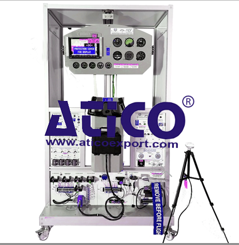
Advanced Cockpit Instrumentation Traine...
Features: The system combines Cockpit analog flight inst...

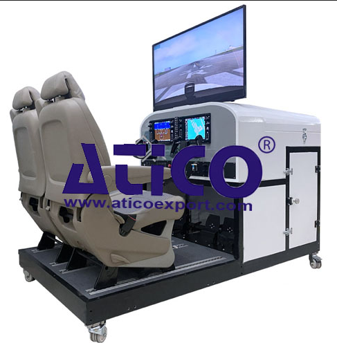
Features: The system combines primary flight instrumentati...

Features: The system combine primary flight instrument...

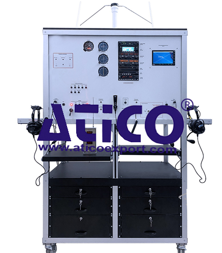
Analogue Cockpit Instrumentation System...
Features: The system combines Cockpit analog flight...
Features: Components: Screen System Two PFD/MFD...
Features: The system combines Navigation (ADF-DME-VOR-IL...
Features: The system combines Navigation (ADF-DME-VOR-IL...
Copyrights © 2025 All Rights Reserved by Atico
Product
Reviews
add Review
reviews
No Review Yet.