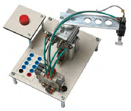
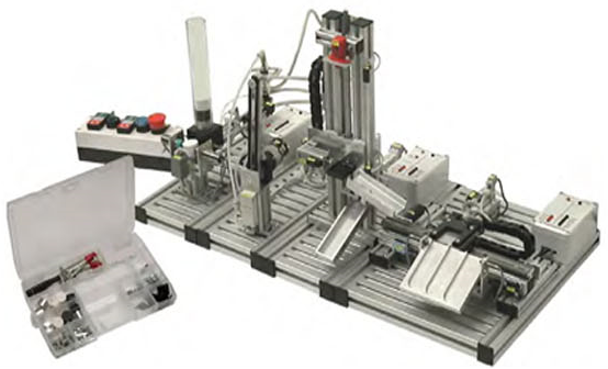
Manipulating Arm
Categories: Automation TechnologiesManipulating arm is designed to grab and release pieces in two different positions. It includes a double effect cylinder to move the piece up and down, a rotary cylinder to transport the piece b...


Product
Description
quick overview :
Product
Reviews
add Review
reviews
No Review Yet.
Related
Products
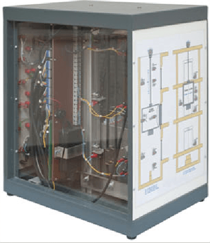
The unit is a tabletop structure reproducing a 3-floor lift....
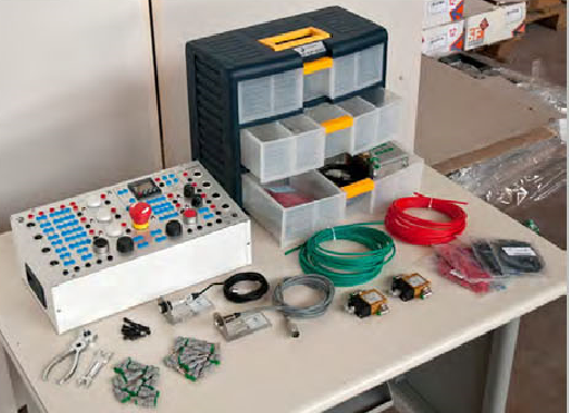
Advanced Electro-Pneumatics Kit
This advanced pneumatics kit is supplied only as an extensio...
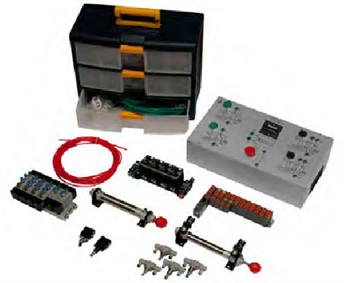
This Advanced pneumatics kit is supplied only as an extensio...
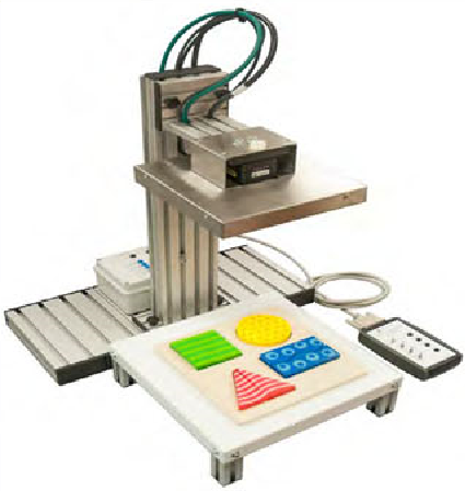
Artificial Colour Vision System
System, included in a laboratory of automation technologies,...
Automatic Multilevel Storage for Product...
The mechatronic system consists of the following elements:•...
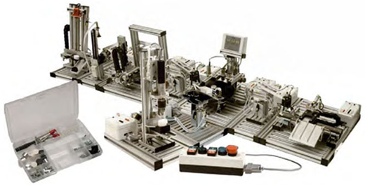
Automatic Multistation Line for Samples...
The mechatronic system consists of the following elements:•...
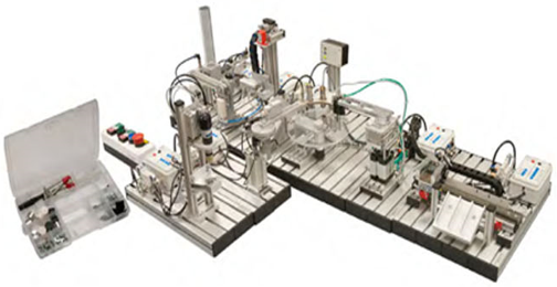
Automatic Pieces identification and Sele...
The mechatronic system consists of the following elements:•...
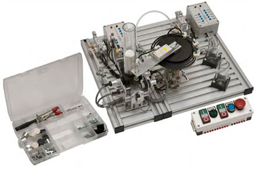
Automatic Pieces Identification, Thickne...
The mechatronic system consists of the following elements:•...
Copyrights © 2025 All Rights Reserved by Atico
Product
Reviews
add Review
reviews
No Review Yet.