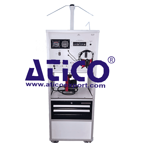
Navigation & Magnetic Compass Trainer
Categories: Aviation Maintenance Training EquipmentFeatures: Fully functional and configured like a typical Navigation Fully functional and configured like a typicalMagnetic Compass Compass System provides the pilot with a simple,...


Product
Description
Features:
- Fully functional and configured like a typical Navigation
- Fully functional and configured like a typicalMagnetic Compass
- Compass System provides the pilot with a simple,
comprehensive visual display of the heading and position in
relation to a desired course.
- Complete slaved compass system that includes a
magnetic slaving transmitter, a slaving control and compensator unit, a
directional gyro for stabilization of the system, and the Pictorial
Navigation Indicator (PNI) itself.
- Combine the display functions of the standard
Directional Gyro with VOR/LOC course deviation indication and Glideslope
deviation and flag into one compact display.
- The Pictorial Navigation Indicator provides a
pictorial display of the horizontal navigation situation. Also provides
manual controls for course and heading datum selections. Outputs from the
system are for automatic pilot or flight director, VOR receivers and
additional compass loads
- The Directional Gyro is a remote mounted unit which,
in conjunction with the Magnetic Azimuth Transmitter, provides a
gyro-stabilized magnetic heading to the system Indicator. In addition to
the slaving circuitry this unit contains an internal power supply which
provides excitation voltages for the Magnetic Azimuth Transmitter and
positive and negative D.C. voltages for the Pictorial Navigation Indicator
and the Slaving Accessory.
- The Magnetic Azimuth Transmitter senses the direction
of the earth’s magnetic field and transmits this information to the
Pictorial Navigation Indicator.
- The Slaving Accessory is a panel mounted unit which
contains the slaving meter, slaving switches, and corrector circuitry
which compensates for the effect of local magnetic disturbances on the
Magnetic Azimuth Transmitter.
- The trainer should allow trainees to understand
fundamentals of magnetic compass system and its components.
- The system mounted on a metal/aluminum mobile stand.
- Metal/aluminum frame with 4 wheels. 2 of 4 wheels are
lockable.
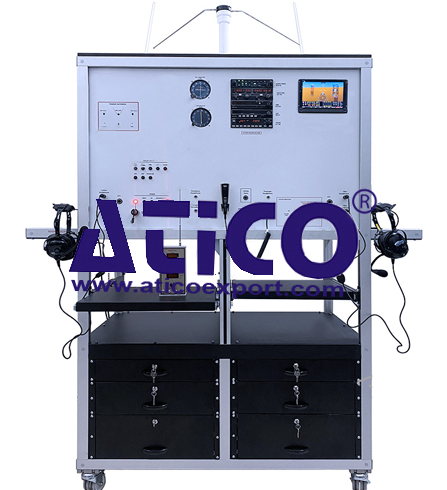
Components:
1.
NAV/COM Device
2. Pictorial
Navigation Indicator (HSI)
3. Directional
Gyro
4. Flux
Detector (The Magnetic Azimuth Transmitter)
5. Slaving
Accessory
6. NAV
Antenna
7. COM
Antenna
8. Digital
instrument
9. DC
Power Box
10. Circuit
Breaker
Components
Technical Specs
- NAV/COMM device
- Solid state, gas discharge digital
display NAV/COMM Transceiver
- 720 or 760 frequency COMM available
- 200-channel NAV receiver
- Built-in VOR Converter
- Maximum 25 kHz channel spacing (It
should be 8.33 kHz)
- Frequency (COM) range should be
minimum 118.000 to 136.975
- Nav receiver frequency range: 108.00
MHz to 117.95 MHz in 50 kHz increments
- VOR/LOC converter accuracy:
- VOR – Typical bearing error of less
than 0.5° with precision track selector (2° max. error)
- LOC–Typical centering error of less
than 3μA (7μA max. error).
- Receiver selectivity:
- 6dB at 34.8 kHz minimum
- 80dB at 84.0 kHz maximum
- Input voltage range should
be 14 or 28 VDC
- Operating temperature range should
be minimum -18 to +50 C
- There should be Built-in
VOR/Localizer converter in NAV/COMM device
- VOR receiver displays to/from and
radial
- Active and standby flip-flop
frequencies
- Volume control
- Frequency memory and recall
- Display
- Output should be minimum 10 watt
- Frequency stability: ±0.0015%
- Adjustable up to 100mW into 500 ohms
headphones
- 6dB bandwidth ± 8.1 kHz
- 60dB bandwidth ± 20.0 kHz
- Physical dimensions:
- Width: 6.25 inches (15.88 cm)
Height: 2.05 inches (5.21 cm) Depth: 10.16 inches (25.81 cm) including
connector
- There should be an original
installation manual.
- Pictorial Navigation Indicator
- Lubber Line
- Nav Warning Flag
- Heading Select Bug
- Compass warning Flag
- Selected Course pointer
- To/From indicator
- GS Deviation Scale
- Compass Card
- VOR/LOC Deviation Bar
- One (1) headset
- 24 dB NRR hearing protection
- 3.5mm Music input port
- EM56 noise reflective cup mic
- Clear Hear performance audio
speakers
- Foam Fit comfort ear seals
- Deep Pocket ear canals
- Wind block foam mic muff
- Stainless steel adjustable headband
- Trainer should a DYNAMIC MICROPHONE
- Impedance: 50-600 ohms.
- Includes: 5 ft. coiled cord with
right-angle plug and hanger bracket.
- Trainer should have VOR/LOC antenna
- Frequency should be at least 108 to
118 MHz and 328-336MHz
- Impedance should be 50 Ohms
- Pattern should be Omni-Directional
- Antenna should have an original
cable
- Trainer should have VHF-COM antenna
- Frequency 118 to 137 MHZ
- Polarization and Vertical
- Impedance 50 Ohms
- Connector – BNC Female
- Antenna should have an original
cable
- Directional Gyro
- Remote mounted
- Original Mounted Tray
- Power: 14-volt or 28-volt dc
- 300-degree free turn able system for
testing
- Flux Detector (The Magnetic Azimuth Transmitter)
- Slaving Accessory
- Slave/Free Gyro Switch
- Slaving Meter indicator
- CW/CCW Adjustment
- Digital instrument for Gyro degree
- Size: Min 7 inch
- Touchable
- Real Times
- Magnetic Compass
quick overview :
Features:
- Fully functional and configured like a typical Navigation
- Fully functional and configured like a typicalMagnetic Compass
- Compass System provides the pilot with a simple,
comprehensive visual display of the heading and position in
relation to a desired course.
- Complete slaved compass system that includes a
magnetic slaving transmitter, a slaving control and compensator unit, a
directional gyro for stabilization of the system, and the Pictorial
Navigation Indicator (PNI) itself.
- Combine the display functions of the standard
Directional Gyro with VOR/LOC course deviation indication and Glideslope
deviation and flag into one compact display.
- The Pictorial Navigation Indicator provides a
pictorial display of the horizontal navigation situation. Also provides
manual controls for course and heading datum selections. Outputs from the
system are for automatic pilot or flight director, VOR receivers and
additional compass loads
- The Directional Gyro is a remote mounted unit which,
in conjunction with the Magnetic Azimuth Transmitter, provides a
gyro-stabilized magnetic heading to the system Indicator. In addition to
the slaving circuitry this unit contains an internal power supply which
provides excitation voltages for the Magnetic Azimuth Transmitter and
positive and negative D.C. voltages for the Pictorial Navigation Indicator
and the Slaving Accessory.
- The Magnetic Azimuth Transmitter senses the direction
of the earth’s magnetic field and transmits this information to the
Pictorial Navigation Indicator.
- The Slaving Accessory is a panel mounted unit which
contains the slaving meter, slaving switches, and corrector circuitry
which compensates for the effect of local magnetic disturbances on the
Magnetic Azimuth Transmitter.
- The trainer should allow trainees to understand
fundamentals of magnetic compass system and its components.
- The system mounted on a metal/aluminum mobile stand.
- Metal/aluminum frame with 4 wheels. 2 of 4 wheels are
lockable.
Components:
1.
NAV/COM Device
2. Pictorial
Navigation Indicator (HSI)
3. Directional
Gyro
4. Flux
Detector (The Magnetic Azimuth Transmitter)
5. Slaving
Accessory
6. NAV
Antenna
7. COM
Antenna
8. Digital
instrument
9. DC
Power Box
10. Circuit
Breaker
Components
Technical Specs
- NAV/COMM device
- Solid state, gas discharge digital
display NAV/COMM Transceiver
- 720 or 760 frequency COMM available
- 200-channel NAV receiver
- Built-in VOR Converter
- Maximum 25 kHz channel spacing (It
should be 8.33 kHz)
- Frequency (COM) range should be
minimum 118.000 to 136.975
- Nav receiver frequency range: 108.00
MHz to 117.95 MHz in 50 kHz increments
- VOR/LOC converter accuracy:
- VOR – Typical bearing error of less
than 0.5° with precision track selector (2° max. error)
- LOC–Typical centering error of less
than 3μA (7μA max. error).
- Receiver selectivity:
- 6dB at 34.8 kHz minimum
- 80dB at 84.0 kHz maximum
- Input voltage range should
be 14 or 28 VDC
- Operating temperature range should
be minimum -18 to +50 C
- There should be Built-in
VOR/Localizer converter in NAV/COMM device
- VOR receiver displays to/from and
radial
- Active and standby flip-flop
frequencies
- Volume control
- Frequency memory and recall
- Display
- Output should be minimum 10 watt
- Frequency stability: ±0.0015%
- Adjustable up to 100mW into 500 ohms
headphones
- 6dB bandwidth ± 8.1 kHz
- 60dB bandwidth ± 20.0 kHz
- Physical dimensions:
- Width: 6.25 inches (15.88 cm)
Height: 2.05 inches (5.21 cm) Depth: 10.16 inches (25.81 cm) including
connector
- There should be an original
installation manual.
- Pictorial Navigation Indicator
- Lubber Line
- Nav Warning Flag
- Heading Select Bug
- Compass warning Flag
- Selected Course pointer
- To/From indicator
- GS Deviation Scale
- Compass Card
- VOR/LOC Deviation Bar
- One (1) headset
- 24 dB NRR hearing protection
- 3.5mm Music input port
- EM56 noise reflective cup mic
- Clear Hear performance audio
speakers
- Foam Fit comfort ear seals
- Deep Pocket ear canals
- Wind block foam mic muff
- Stainless steel adjustable headband
- Trainer should a DYNAMIC MICROPHONE
- Impedance: 50-600 ohms.
- Includes: 5 ft. coiled cord with
right-angle plug and hanger bracket.
- Trainer should have VOR/LOC antenna
- Frequency should be at least 108 to
118 MHz and 328-336MHz
- Impedance should be 50 Ohms
- Pattern should be Omni-Directional
- Antenna should have an original
cable
- Trainer should have VHF-COM antenna
- Frequency 118 to 137 MHZ
- Polarization and Vertical
- Impedance 50 Ohms
- Connector – BNC Female
- Antenna should have an original
cable
- Directional Gyro
- Remote mounted
- Original Mounted Tray
- Power: 14-volt or 28-volt dc
- 300-degree free turn able system for
testing
- Flux Detector (The Magnetic Azimuth Transmitter)
- Slaving Accessory
- Slave/Free Gyro Switch
- Slaving Meter indicator
- CW/CCW Adjustment
- Digital instrument for Gyro degree
- Size: Min 7 inch
- Touchable
- Real Times
- Magnetic Compass
Product
Reviews
add Review
reviews
No Review Yet.
Related
Products
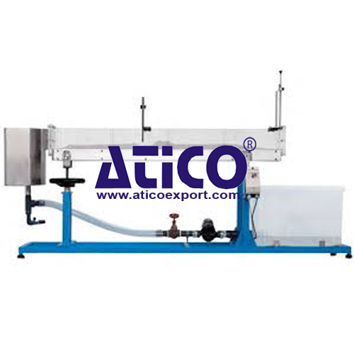
Sediment Transport Demonstration Channel
Specification: A transparent, inclinable flow channel thr...
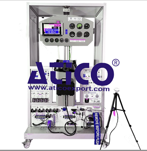
Advanced Cockpit Instrumentation Traine...
Features: The system combines Cockpit analog flight inst...
Features: The system combines primary flight instrumentati...

Features: The system combine primary flight instrument...

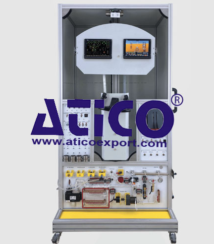
Analogue Cockpit Instrumentation System...
Features: The system combines Cockpit analog flight...
Features: Components: Screen System Two PFD/MFD...

Features: The system combines Navigation (ADF-DME-VOR-IL...
Features: The system combines Navigation (ADF-DME-VOR-IL...
Copyrights © 2025 All Rights Reserved by Atico
Product
Reviews
add Review
reviews
No Review Yet.