Two-Shaft Gas Turbine
Categories: Automation TechnologiesDescription A self-contained, fully instrumented, educational two shaft gas turbine. Powered by kerosene, the experimental abilities of this high-quality apparatus enable comprehensive practical inve...


Product
Description
Description
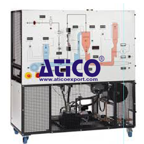
A self-contained, fully instrumented, educational two shaft gas turbine. Powered by kerosene, the experimental abilities of this high-quality apparatus enable comprehensive practical investigations into the principles, and performance of two-shaft gas turbines. This product helps students to understand the use of this ‘engine’ with a secondary power turbine, on practical applications such as helicopters or electrical power generators. A steel frame holds a gas generator, power turbine, combustion chamber, oil and fuel tanks, pumps, ancillaries and guards. Above these is an instrumentation and control panel with schematic diagram. The clearly labelled control panel with mimic diagram includes the instrument displays, controls and warning lights. Air passes through a calibrated nozzle and air box, into a compressor, then into the combustion chamber. A pump transfers fuel from the fuel tank to spray through a special nozzle into the combustion chamber. A high energy spark ignites the air and fuel mixture, that flows to a gas generator turbine. The combustion chamber gives excellent combustion, low pressure loss and good flame stability over a wide range of conditions. A fuel flow control valve on the instrumentation and control panel regulates the turbine speed. This design reduces the possibility of overspeed. Hot gas from the gas generator turbine passes through a short duct to the power turbine. The short duct reduces heat losses to atmosphere. The exhaust gases then discharge to a suitable exhaust system. The power turbine couples direct to an eddy current dynamometer, so there are no belts to adjust. A load cell on the dynamometer measures torque and a sensor measures the dynamometer speed, to allow calculation of true shaft power. A control on the instrumentation and control panel adjusts the load of the dynamometer (and therefore speed of the power turbine). The equipment has an oiling system including filters and water-cooled oil. A PLC (programmable logic controller) controls the turbine start up and shut down. For protection of the equipment and user, it shuts down the turbines if the user makes an error. It also switches on cooling fans after running. Digital and analogue indicators show all the important readings from the sensors around the equipment, such as pressures, temperatures, fuel fl ow and level. This equipment connects to your computer (computer not supplied) and includes specialist, user-friendly data acquisition software. This allows students to display, graph and analyse all relevant variables, and save their results for later analysis. Supplied on a CD-ROM, the data acquisition system includes a connection cable. we supply a detailed textbook with the equipment. The textbook covers the theory and use of gas turbines.
Learning Outcomes
Turbine tests to find key performance information such as:
Specific fuel consumption
Pressure losses and ratios
Thermal, isentropic and mechanical efficiencies
Work and power
Specifications
ATICO is committed to a programme of continuous improvement; hence we reserve the right to alter the design and product specifi cation without prior notice.
Nett dimensions and weight: 1385 mm (width) x 825 mm (depth) x 1721 mm (height) and
360 kg (with no fuel or oil)
Approximate packed dimensions and weight: 4.12 m3 and 460 kg
Fuel:
High-quality aviation kerosene: ASTM D 1655 Jet A or similar
Lubricating oil: 10W-40 multigrade turbo diesel oil
Gas generator turbine:
Maximum continuous speed:
Approximately 90000 rev.min–1
Power turbine (and dynamometer):
Maximum continuous speed: 40 000 rev.min–1
Instruments:
• Shaft speeds
• Pressures
• Temperatures
• Torque
• Fuel flow, level and pressure
• Oil temperature and pressure
• Dynamometer brake load
• Total hours run
Automatic shut down conditions:
• Ignition failure
• Incorrect turbine speeds
• Oil pressure failure
• Water supply failure
• Incorrect temperatures
Exhaust emissions (typical):
• Carbon dioxide (CO2): 1.8 – 2.9%
• Carbon monoxide, (CO): 240 – 900 ppm
• Nitric oxide, (NO): 11 – 26 ppm
• Nitrogen dioxide, (NO2): 0 – 1 ppm
• Combination of NO and NO2, (NOX): 12 – 26 ppm
• Sulphur dioxide, (SO2): 5 – 6 ppm
Operating Conditions
Operating Enviroment:
Dry and well-ventilated engine test laboratories
Storage Temprature Range :
–25°C to +55°C (when packed for transport)
Operating Temprature range:
+5°C to +35vC
Note: The fl ash point of kerosene can be as low as 37°C, so keep your working environment below 35°C.
Operating relative humidity range:
30% to 95% (non-condensing)
quick overview :
Description
A self-contained, fully instrumented, educational two shaft gas turbine. Powered by kerosene, the experimental abilities of this high-quality apparatus enable comprehensive practical investigations into the principles, and performance of two-shaft gas turbines. This product helps students to understand the use of this ‘engine’ with a secondary power turbine, on practical applications such as helicopters or electrical power generators. A steel frame holds a gas generator, power turbine, combustion chamber, oil and fuel tanks, pumps, ancillaries and guards. Above these is an instrumentation and control panel with schematic diagram. The clearly labelled control panel with mimic diagram includes the instrument displays, controls and warning lights. Air passes through a calibrated nozzle and air box, into a compressor, then into the combustion chamber. A pump transfers fuel from the fuel tank to spray through a special nozzle into the combustion chamber. A high energy spark ignites the air and fuel mixture, that flows to a gas generator turbine. The combustion chamber gives excellent combustion, low pressure loss and good flame stability over a wide range of conditions. A fuel flow control valve on the instrumentation and control panel regulates the turbine speed. This design reduces the possibility of overspeed. Hot gas from the gas generator turbine passes through a short duct to the power turbine. The short duct reduces heat losses to atmosphere. The exhaust gases then discharge to a suitable exhaust system. The power turbine couples direct to an eddy current dynamometer, so there are no belts to adjust. A load cell on the dynamometer measures torque and a sensor measures the dynamometer speed, to allow calculation of true shaft power. A control on the instrumentation and control panel adjusts the load of the dynamometer (and therefore speed of the power turbine). The equipment has an oiling system including filters and water-cooled oil. A PLC (programmable logic controller) controls the turbine start up and shut down. For protection of the equipment and user, it shuts down the turbines if the user makes an error. It also switches on cooling fans after running. Digital and analogue indicators show all the important readings from the sensors around the equipment, such as pressures, temperatures, fuel fl ow and level. This equipment connects to your computer (computer not supplied) and includes specialist, user-friendly data acquisition software. This allows students to display, graph and analyse all relevant variables, and save their results for later analysis. Supplied on a CD-ROM, the data acquisition system includes a connection cable. we supply a detailed textbook with the equipment. The textbook covers the theory and use of gas turbines.
Learning Outcomes
Turbine tests to find key performance information such as:
Specific fuel consumption
Pressure losses and ratios
Thermal, isentropic and mechanical efficiencies
Work and power
Specifications
ATICO is committed to a programme of continuous improvement; hence we reserve the right to alter the design and product specifi cation without prior notice.
Nett dimensions and weight: 1385 mm (width) x 825 mm (depth) x 1721 mm (height) and
360 kg (with no fuel or oil)
Approximate packed dimensions and weight: 4.12 m3 and 460 kg
Fuel:
High-quality aviation kerosene: ASTM D 1655 Jet A or similar
Lubricating oil: 10W-40 multigrade turbo diesel oil
Gas generator turbine:
Maximum continuous speed:
Approximately 90000 rev.min–1
Power turbine (and dynamometer):
Maximum continuous speed: 40 000 rev.min–1
Instruments:
• Shaft speeds
• Pressures
• Temperatures
• Torque
• Fuel flow, level and pressure
• Oil temperature and pressure
• Dynamometer brake load
• Total hours run
Automatic shut down conditions:
• Ignition failure
• Incorrect turbine speeds
• Oil pressure failure
• Water supply failure
• Incorrect temperatures
Exhaust emissions (typical):
• Carbon dioxide (CO2): 1.8 – 2.9%
• Carbon monoxide, (CO): 240 – 900 ppm
• Nitric oxide, (NO): 11 – 26 ppm
• Nitrogen dioxide, (NO2): 0 – 1 ppm
• Combination of NO and NO2, (NOX): 12 – 26 ppm
• Sulphur dioxide, (SO2): 5 – 6 ppm
Operating Conditions
Operating Enviroment:
Dry and well-ventilated engine test laboratories
Storage Temprature Range :
–25°C to +55°C (when packed for transport)
Operating Temprature range:
+5°C to +35vC
Note: The fl ash point of kerosene can be as low as 37°C, so keep your working environment below 35°C.
Operating relative humidity range:
30% to 95% (non-condensing)
Product
Reviews
add Review
reviews
No Review Yet.
Related
Products
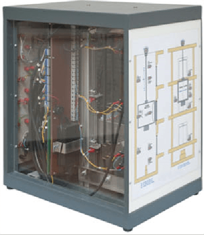
The unit is a tabletop structure reproducing a 3-floor lift....
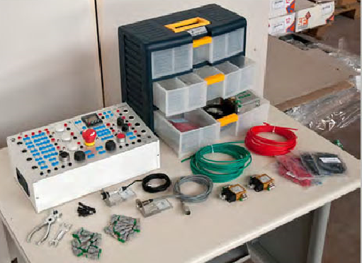
Advanced Electro-Pneumatics Kit
This advanced pneumatics kit is supplied only as an extensio...
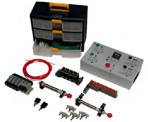
This Advanced pneumatics kit is supplied only as an extensio...

Artificial Colour Vision System
System, included in a laboratory of automation technologies,...
Automatic Multilevel Storage for Product...
The mechatronic system consists of the following elements:•...
Automatic Multistation Line for Samples...
The mechatronic system consists of the following elements:•...
Automatic Pieces identification and Sele...
The mechatronic system consists of the following elements:•...
Automatic Pieces Identification, Thickne...
The mechatronic system consists of the following elements:•...
Product
Reviews
add Review
reviews
No Review Yet.